

Remote-phosphor led downlight
a technology of led downlights and led downlights, which is applied in the direction of semiconductor devices for light sources, fixed installations, lighting and heating apparatus, etc., can solve the problems of difficult lighting applications, low efficiency, and low luminance of downlights, and achieves low heat energy concentration, low luminance, and elimination or substantially reducing any glare factor
- Summary
- Abstract
- Description
- Claims
- Application Information
AI Technical Summary
Benefits of technology
Problems solved by technology
Method used
Image

Examples
first embodiment
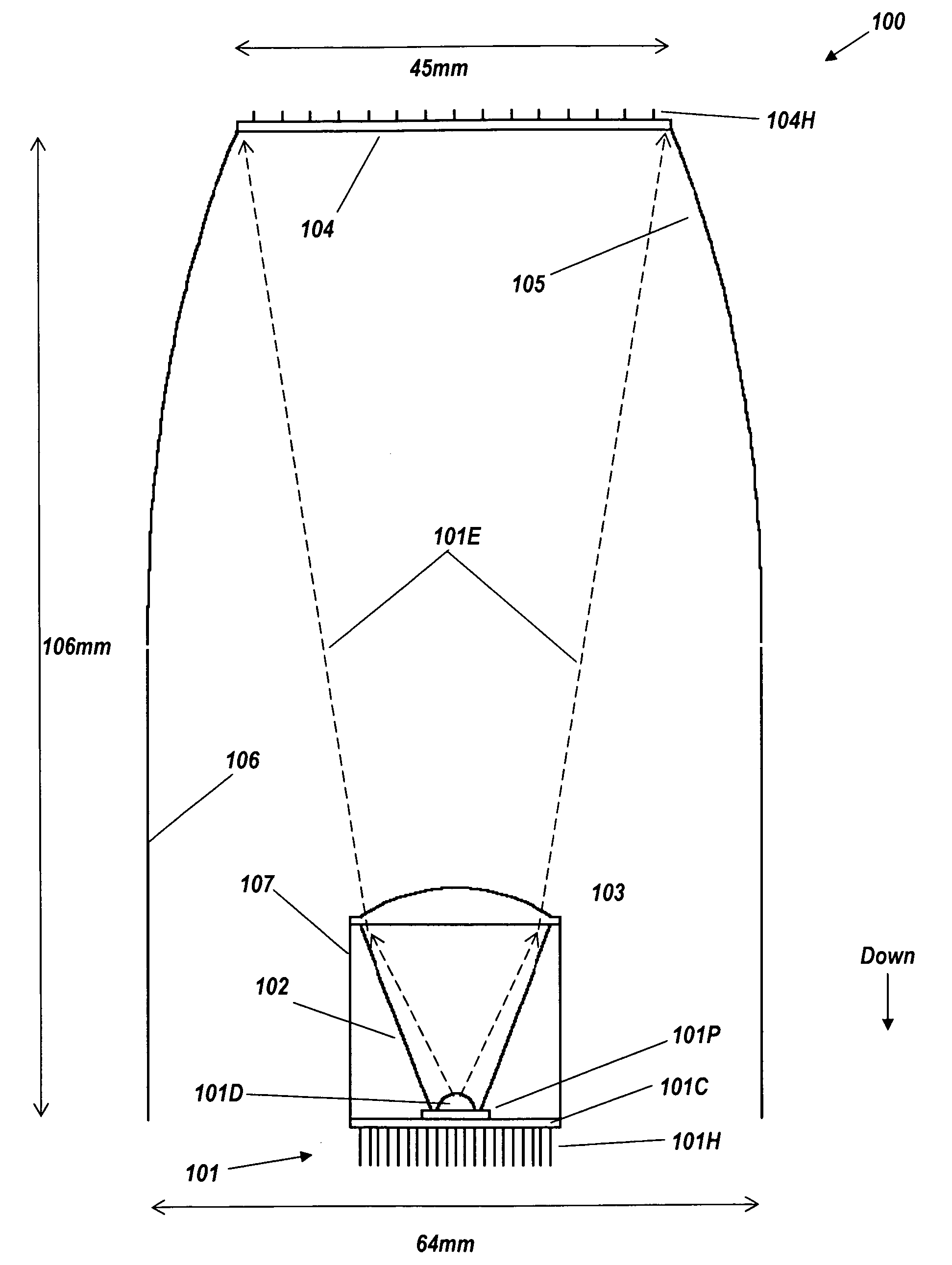
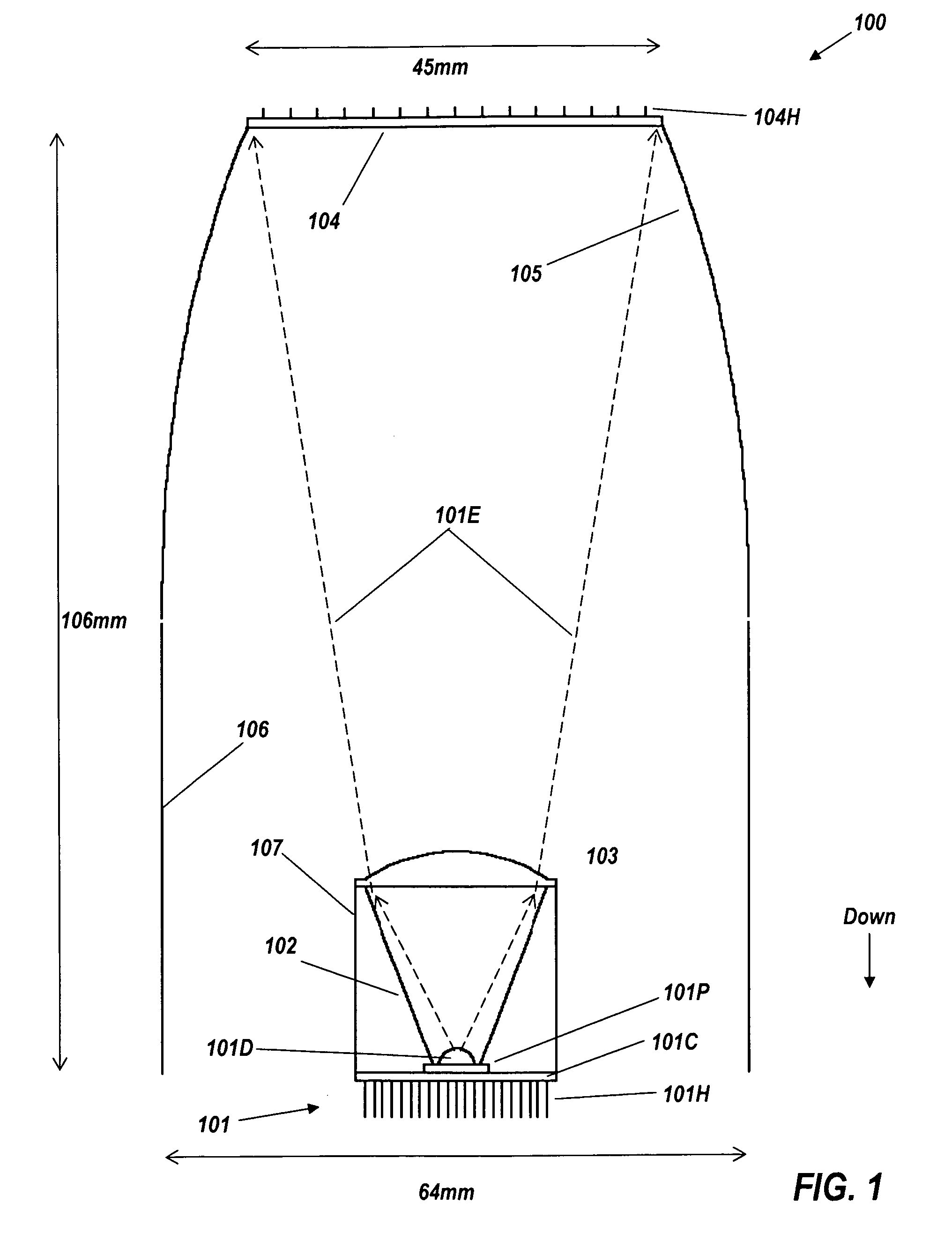
[0031]FIG. 1 is a cross-section view of a remote-phosphor LED luminaire 100, comprising light source 101 (comprising transparent dome 101 D from which emission 101E originates, LED package 101P, circuit board 101P, and rear heat exchanger 101H), reflective cone 102, plano-convex lens 103, remote phosphor 104, and ideal beam-forming reflector 105. Cylindrical shroud 106 extends downward from reflector 105, to surround cone 102, and has the same reflective coating as reflector 105 to ensure that rays encountering it will stay within the output beam. To ease understanding of the drawing, cylindrical shroud 106 is drawn in FIG. 1 as artificially separated from the profile of reflector 105. However, in a practical embodiment there is no gap between them, and they may be manufactured in a single piece. Cylindrical outer reflector 107 surrounding cone 102 ensures that rays from phosphor 104 or reflector 105, 106 encountering reflector 107 will stay within the output beam. The shroud and re...
second embodiment
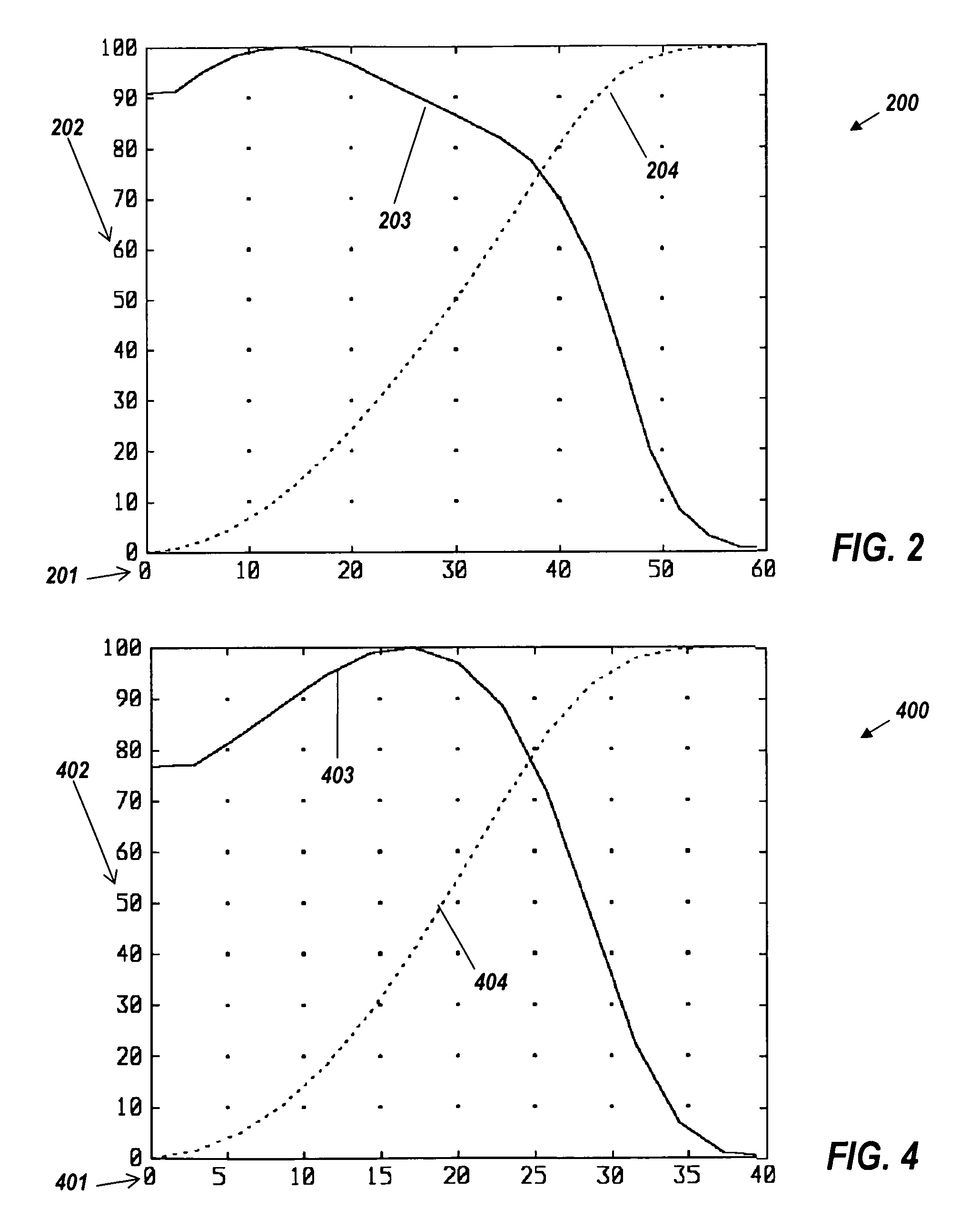
[0038]FIG. 3 is a cross-section view of a remote-phosphor LED downlight. FIG. 3 shows luminaire 300, comprising blue light source 301 (comprising transparent dome 301D, LED package 301P,and rear heat exchanger 301H), conical reflector 302, plano-convex lens 303, remote phosphor 304, and ideal reflector 305, a slightly truncated CPC with a 30° acceptance / output angle. As shown in FIG. 3, cone frustum 302 has an axial length of 21 mm. Lens 303 and the wide end of cone 302 have a diameter of 20 mm. Cone 302 and lens 303 could be replaced by any suitable collimator that produces an output beam no wider in angle than ±30°. Dotted line 304E denotes the emission of remote phosphor 304, confined by reflector 305 to ±30°. Narrower output angles, for example, down to ±20°, are equally feasible if greater overall depth and width are allowed. As shown in FIG. 3, luminaire 300 is 106 mm high, 90 mm wide across the output end, and 45 mm wide across the phosphor end.
[0039]FIG. 4 shows the far-fiel...
third embodiment
[0043]FIG. 5 shows a perspective cutaway view of a third embodiment, of a luminaire 500 with some of its key components as it would be seen from below. Remote-phosphor luminaire 500 comprises an outer cylindrical shroud 501, the interior surface of which acts as a reflector, and spider 502 supporting the light engine 503. The light engine 503 comprises conical reflector 503R, plano-convex lens 503L, transparent dome 503D, multi-chip LED package 503P, circuit board 503C, driver module 503D, power wire 503W, and multi-rod heat sink 503H on the underside of the light engine, which is encased in an exterior cylindrical reflector 504. External CPC 504 holds spider 502 and remote phosphor (not shown) with its cylinder-finned heat exchanger 505.
[0044]Spider 502 has internal features on one or more of its three vanes (two shown) to enclose the wiring 503W. The arms of spider 502 are preferably sharp-edged on the edge towards the remote phosphor 104, 304 and coated with high-reflectivity mat...
PUM
 Abstract
Description
Claims
Application Information