System and Method for Providing Adaptive Dead Times

a dead time and dead time technology, applied in the field of system and a method for power supplies, can solve problems such as no longer exis

Active Publication Date: 2009-11-05
INFINEON TECH AUSTRIA AG
View PDF14 Cites 54 Cited by
  • Summary
  • Abstract
  • Description
  • Claims
  • Application Information

AI Technical Summary

Problems solved by technology

However, if the dead time's duration is too long (or too short), then the ZVS condition may no longer exist (or may have not yet occurred).

Method used


Image

  • System and Method for Providing Adaptive Dead Times
  • System and Method for Providing Adaptive Dead Times
  • System and Method for Providing Adaptive Dead Times

Examples


Embodiment Construction

[0024]The making and using of the presently preferred embodiments are discussed in detail below. It should be appreciated, however, that the present invention provides many applicable inventive concepts that can be embodied in a wide variety of specific contexts. The specific embodiments discussed are merely illustrative of specific ways to make and use the invention, and do not limit the scope of the invention.

[0025]The present invention will be described with respect to preferred embodiments in a specific context, namely a fluorescent lamp electronic ballast. The invention may also be applied, however, to other applications, such as other lamp ballasts like a high intensity discharge (HID) ballast or an LLC converter used in a switching power supply for applications such as notebook computers, flat panel displays, and so forth.

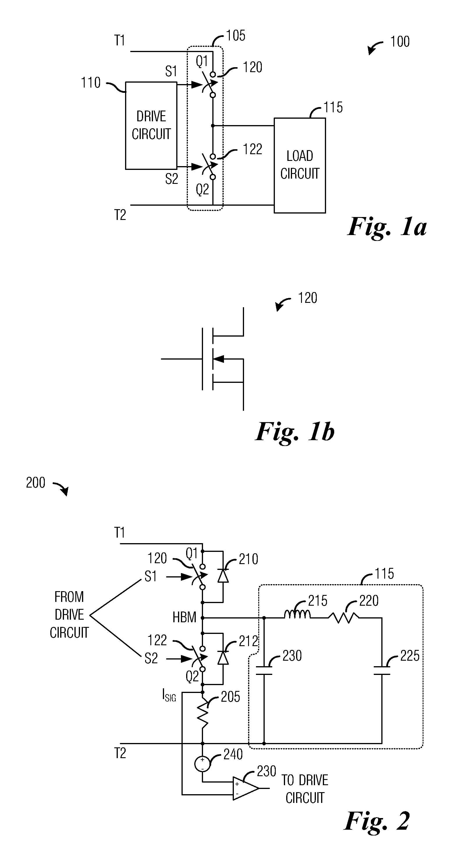
[0026]With reference now to FIG. 2, there is shown a diagram of an electronic ballast 200 for a fluorescent lamp, wherein the electronic ballast 200 is capa...


PUM


Abstract

System and method for adaptively altering a power supply's dead time. A method comprises detecting a start of a dead time, detecting an ending condition of the dead time, and ending the dead time. The detecting of the ending condition is based on a first current flowing through a lower portion of the power supply or a second current flowing through a gate driver of a lower switching element in the power supply.

Description

TECHNICAL FIELD[0001]The present invention relates generally to a system and a method for power supplies, and more particularly to a system and a method for adaptively altering a power supply's dead time.BACKGROUND[0002]FIG. 1a illustrates a fluorescent lamp's electronic ballast 100. The electronic ballast 100 includes a half-bridge circuit 105, a drive circuit 110, and a load circuit 115. The half-bridge circuit 105 may include two semiconductor switching elements, Q1120 and Q2122, which are connected in series with respect to voltage supply terminals T1 and T2 of a voltage supply that supplies a direct current (DC) voltage with potential Vb. The drive circuit 110 generates two control signals, S1 and S2, that may be used to control the state of the two semiconductor switching elements. FIG. 1b illustrates a semiconductor switching element, such as the semiconductor switching element Q1120. The semiconductor switching element Q1120 may use a wide variety of semiconductor transistor...

Claims


Application Information

Patent Timeline
Patent Type & Authority Applications(United States)
IPC IPC(8): H02M7/48H02M1/00
CPCH02M3/1563H02M1/38Y02B70/10H02M1/0058H02M7/4815H02M3/33571
Inventor FELDTKELLER, MARTIN
Owner INFINEON TECH AUSTRIA AG
Why Eureka
Try Eureka