System and method for implementation of layer 2 redundancy protocols across multiple networks

Active Publication Date: 2009-11-05
AVAGO TECH INT SALES PTE LTD
View PDF47 Cites 59 Cited by
  • Summary
  • Abstract
  • Description
  • Claims
  • Application Information

AI Technical Summary

Benefits of technology

[0022]The present invention also discloses a system for providing a loop free Layer 2 topology between a plurality of customer networks and an external network. The system comprises a plurality of customer networks, each customer network implementing a layer 2 redundancy protocol whereby control packets are propagated throughout the plurality of customer networks and used by one or more network devices comprising the plurality of customer networks to maintain a topology free of Layer 2 loops. Each of the plurality of customer networks further comprises a pl

Problems solved by technology

Loops occur when a network has multiple active paths between devices at any given time, resulting in the duplication of messages.
The spanning tree protocol, however, suffers from several limitations when implemented in multiple large interconnected networks.
Standard spanning tree protocol is p

Method used


Image

  • System and method for implementation of layer 2 redundancy protocols across multiple networks
  • System and method for implementation of layer 2 redundancy protocols across multiple networks
  • System and method for implementation of layer 2 redundancy protocols across multiple networks

Examples


Embodiment Construction

[0035]Embodiments of a method, system, and article of manufacture comprising software programs for instantiating a plurality of instances of a layer 2 (L2) redundancy protocol or protocols across multiple networks to ensure that each network topology is free of layer 2 loops in accordance with the present invention are described herein with reference to the drawings in FIGS. 1 through 9.

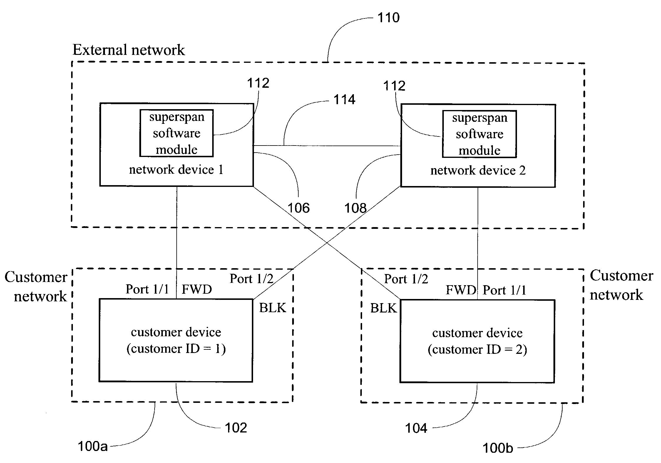
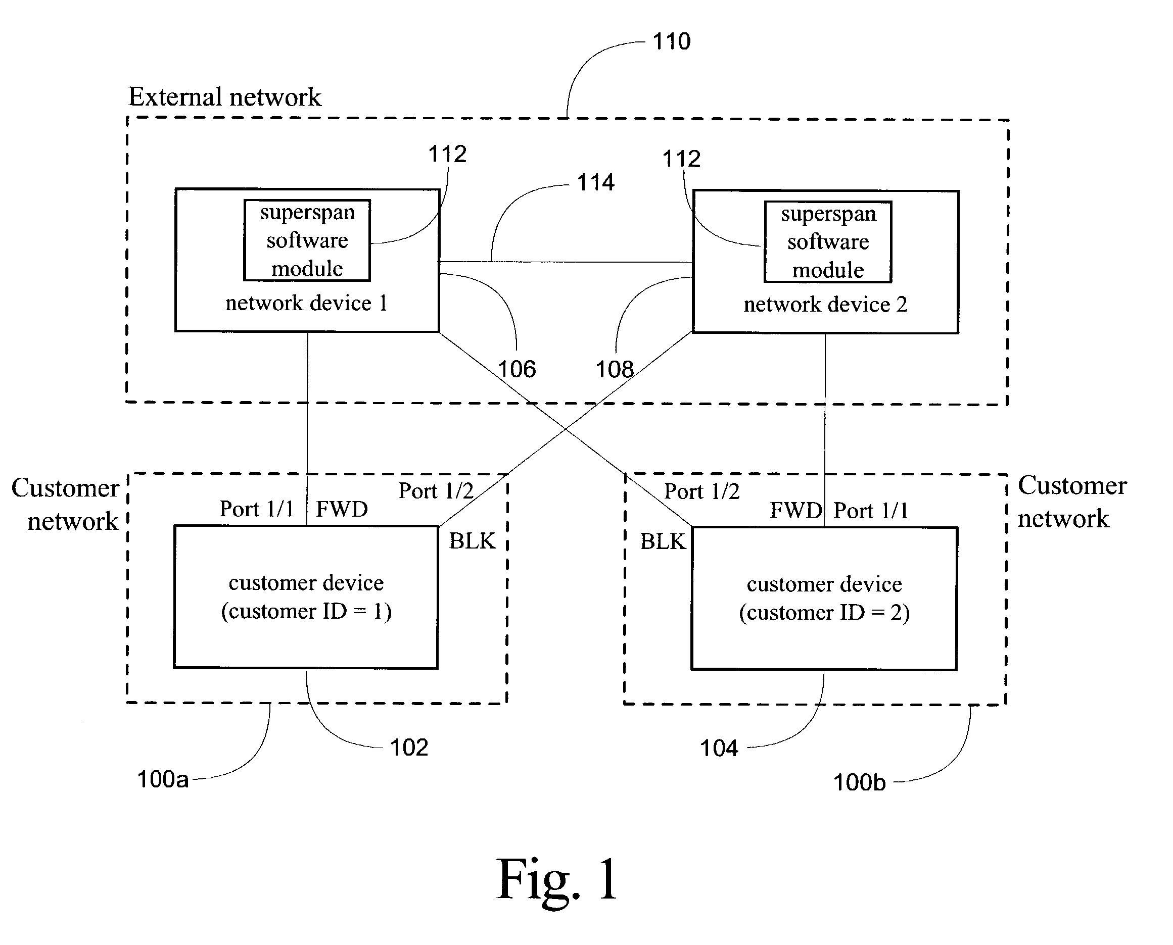
[0036]Turning to FIG. 1, a network topology comprising hardware and software components configured according to one embodiment of the present invention is illustrated. The network topology presented comprises a number of network devices 102, 104, 106 and 108 performing layer 2 aggregation and switching functionality. As is explained in greater detail herein, each of these layer 2 devices 102, 104, 106 and 108 may comprise hubs, switches, bridges or other network interconnection devices. Furthermore, each network device implements one or more instances of a layer 2 redundancy protocol or protocols. Ac...


PUM


Abstract

The system, method, and article of manufacture of the present invention allows multiple customers connected to a common external network to each implement a layer 2 redundancy protocol, such as the spanning tree protocol, in order to prevent layer 2 loops. Accordingly, a method is presented for providing an independent loop free layer 2 topology between a external network and a customer network comprising tagging control packets originating on the customer network with a unique identifier and tunneling the control packets received from the customer network between a plurality of boundary interface devices at the external network such that the control packets are routed back to the customer network based on the presence of the unique identifier in the control packet. The layer 2 redundancy protocol on the customer network converges based at least in part on the presence of control packets appearing on more than one port on the customer network.

Description

RELATED APPLICATIONS[0001]This application is related to the following commonly owned patent applications, each of which applications is hereby incorporated by reference herein in its entirety:[0002]application Ser. No. 10 / 124,449, filed on Apr. 16, 2002 and titled “SYSTEM AND METHOD FOR PROVIDING NETWORK ROUTE REDUNDANCY ACROSS LAYER 2 DEVICES”, attorney docket no. 5372 / 5; and[0003]application Ser. No. 10 / 090,669, filed on Mar. 4, 2002 and titled “NETWORK CONFIGURATION PROTOCOL AND METHOD FOR RAPID TRAFFIC RECOVERY AND LOOP AVOIDANCE IN RING TOPOLOGIES”, attorney docket no. 5372 / 4.COPYRIGHT NOTICE[0004]A portion of the disclosure of this patent document contains material which is subject to copyright protection. The copyright owner has no objection to the facsimile reproduction by anyone of the patent document or the patent disclosure, as it appears in the Patent and Trademark Office patent files or records, but otherwise reserves all copyright rights whatsoever.BACKGROUND OF THE I...

Claims


Application Information

Patent Timeline
IPC IPC(8): H04L12/56H04L45/74
CPCH04L45/74H04L12/66
Inventor KUO, ANDREW TAI-CHINKAMAT, GURUDEEPMONCADA-ELIAS, JORDIHSU, IVY PEI-SHANJALAN, RAJKUMAR
Owner AVAGO TECH INT SALES PTE LTD
Why Eureka
Try Eureka