Multi-channel pipettor with repositionable tips

a multi-channel, pipettor technology, applied in the direction of instruments, analytical using chemical indicators, laboratory glassware, etc., can solve the problems of inaccuracy in the center-to-center spacing of individual tip fittings, well as the off-center drive point, etc., to reduce the maximum ejection force required, facilitate effective and ergonomic tip ejection, and enhance ejection force

Active Publication Date: 2009-11-05
INTEGRA BIOSCI CORP
View PDF12 Cites 89 Cited by
  • Summary
  • Abstract
  • Description
  • Claims
  • Application Information

AI Technical Summary

Benefits of technology

[0009]In another aspect of the invention, the multi-channel pipettor provides an improved ejection mechanism that includes several features to facilitate effective and ergonomic tip ejection. The preferred ejector mechanism includes an ejector push bar having an accelerator portion and a decelerator portion as well as a rocker arm, in manner similar, although modified, to that disclosed in copending patent application entitled “Pipette Tip Ejection Mechanism”, application Ser. No. 11 / 856,193, by Gregory Mathus and Richard Cote, filed Sep. 17, 2007, which is assigned to the assignee of the present application and also incorporated herein by reference. During the beginning of the stroke of the ejector button, the decelerator portion of the ejector push bar engages the rocker arm which in turn engages an ejection mechanism in the lower multi-cylinder assembly. The leverage of the rocker arm provides mechanical advantage to enhance the ejection force during the beginning of the stroke of the ejector button. Towards the bottom of the stroke of the ejector button, the accelerator portion of the push bar engages the ejection mechanism in the lower multi-channel assembly, thereby providing sufficient stroke to ensure ejection of all of the pipette tips. The ejection mechanism for the lower assembly includes, among other features, a lower stripper bar with a continuously varied stripping height, preferably a sinusoidal varying stripping height with a maximum height at the center and at the outermost position for the pipette tips. In this manner, the multiple pipette tips are ejected in pairs and each pair is ejected at a slightly different moment from the other pairs, thereby reducing the maximum ejection force required.

Problems solved by technology

In this design, the complexity of the scissors mechanism, as well as its off-center drive point, can produce inaccuracies in the center-to-center spacing for the individual tip fittings.

Method used


Image

  • Multi-channel pipettor with repositionable tips
  • Multi-channel pipettor with repositionable tips
  • Multi-channel pipettor with repositionable tips

Examples


Embodiment Construction

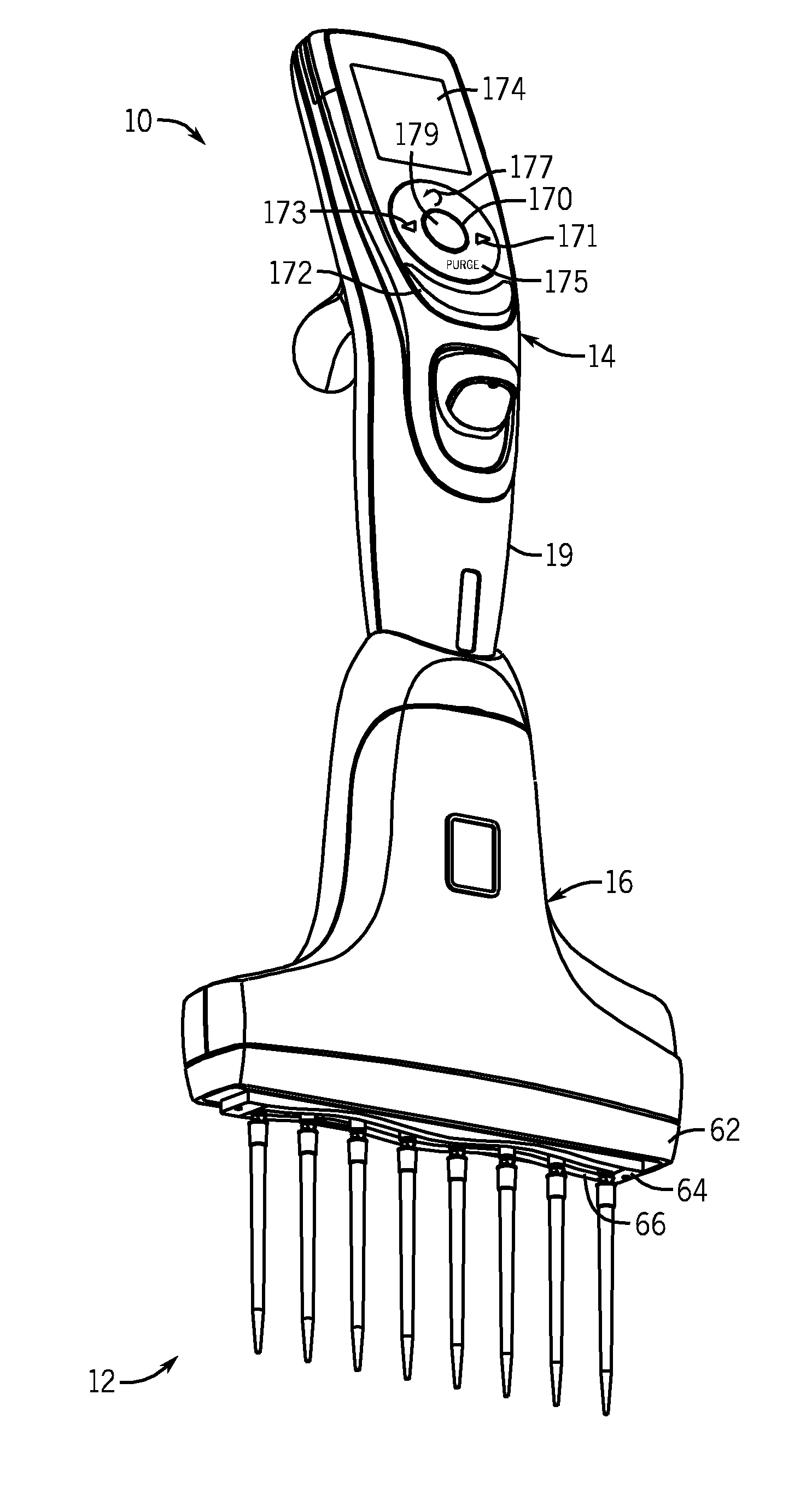
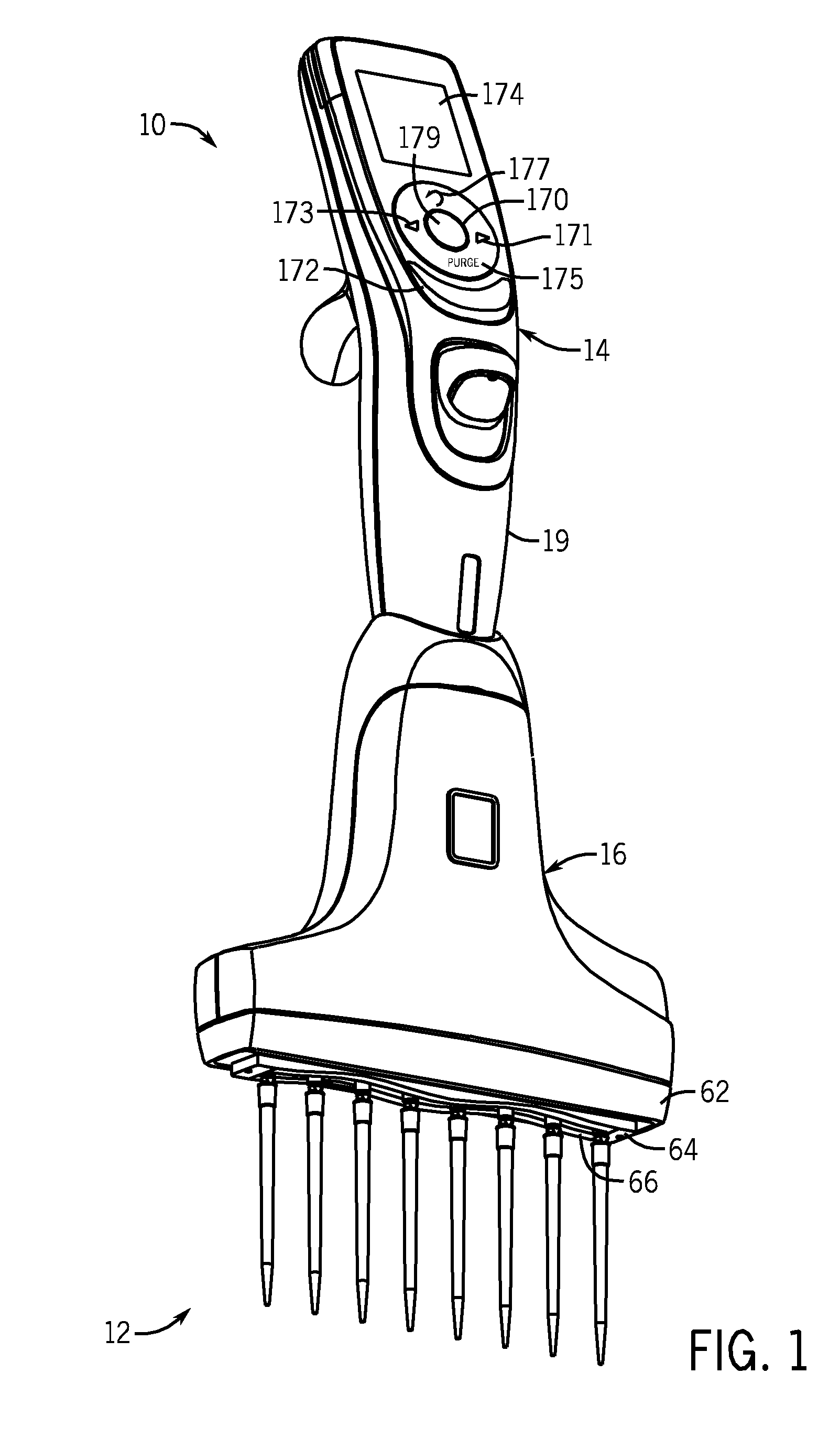
[0027]FIG. 1 illustrates a hand-held, electronic multi-channel pipettor 10 having repositionable pipette tips 12, and constructed in accordance with the preferred embodiment of the invention. The pipettor shown in FIG. 1, as well as the other Figures, illustrates an 8-channel pipettor, however, the invention is not limited to pipettors having eight channels. For example, pipettors having twelve channels, or some other number of channels, are common and are contemplated as being within the scope of the invention.

[0028]The multi-channel pipettor 10 includes an upper handle assembly 14 and a lower multi-channel assembly 16. The pipette tips 12 are mounted to pipette tip fittings or mounting shafts 18, hidden in FIG. 1 but shown clearly in FIG. 6 as well as in other figures. The pipette tips 12, when mounted, generally lie in a vertical plane when the pipettor 10 is held vertically, but are repositionable within the vertical plane in order to change the center-to-center spacing between ...


PUM


Abstract

A hand-held, multi-channel pipettor has an electronically controlled motor to reposition pipette tips for different center to center spacing. Each repositionable tip fitting assembly has a cam following pin that is driven by cam tracks in a motor driven roller drum. Stationary ports for the multiple aspiration cylinders are strategically placed to simplify management of flexible tubes leading to the repositionable pipette tip fitting assemblies. The pipettor has a user interface that can be operated conveniently by one hand to reposition pipette tips. It has a pipette tip ejection mechanism with a sinusoidal stripper bar.

Description

FIELD OF THE INVENTION[0001]The invention relates to hand-held, multi-channel electronic pipettors, and in particular, those having repositionable tip fittings or mounting shafts for disposable pipette tips.BACKGROUND OF THE INVENTION[0002]Hand-held, multi-channel pipettors are designed to enable laboratory workers to transfer multiple samples or reagents from one series of containers to another series of containers, such as from one row of wells in a microtiter plate to another row of wells in another microtiter plate. While some multi-channel pipettors rely on manually powered piston movement for aspirating and dispensing, many use electronically controlled stepper motors to control piston movement for aspirating and dispensing. It is quite common in laboratories to have microtiter plates or well plates with 24, 96, 384, or 1536 wells in an array of rows and columns. Typically, but not always, the center line spacing between wells is 9 mm or some fraction or multiple thereof. Cent...

Claims


Application Information

Patent Timeline
Patent Type & Authority Applications(United States)
IPC IPC(8): B01L3/02
CPCB01L3/0217B01L2200/022B01L3/0237B01L3/0227
Inventor BUTZ, DAVID EARLMATHUS, GREGORYCOTE, RICHARDKALMAKIS, GEORGE P.
Owner INTEGRA BIOSCI CORP
Why Eureka
Try Eureka