Vehicle directional indicator for autonomous and non-autonomous vehicles

a technology for autonomous vehicles and directional indicators, applied in the direction of dashboard lighting devices, vehicle components, electric/fluid circuits, etc., can solve the problems of confusion at such intersections, slow traffic, and the inability of berryhill to disclose a dynamic engagement option for straight directional travel

Active Publication Date: 2019-10-01
HAUSHALTER ALEXA LEA
View PDF24 Cites 2 Cited by
  • Summary
  • Abstract
  • Description
  • Claims
  • Application Information

AI Technical Summary

Benefits of technology

[0007]These purposes are achieved by the vehicle directional signal system and method according to the present invention, wherein a vehicle directional signal indicates a left turn intention of a vehicle, a right turn intention of a vehicle, and a straight ahead directional intention of a vehicle. The straight ahead directional indication is particularly useful at an intersection, where multiple driver and driverless vehicles are computing or evaluating the directional intentions of the other vehicles at an intersection, assured clear distances, oncoming traffic and multiple other traffic patterns, to make the safest and most timely continued travel for themselves.
[0011]The primary advantage provided by the present invention is to indicate to other vehicles and pedestrians, for example at an intersection, the intention of a vehicle to either turn or to continue straight. Another object of the present invention is to provide an additional signal indicator for a vehicle, which can warn other motorists, vehicles and pedestrians of the intent of a human or robot driver, a computer-assisted driver, or a driverless vehicle. Yet another object of the present invention is to provide a safer means of vehicle travel, and help prevent motor vehicle and pedestrian-vehicle accidents. Finally, it is an object of the present invention to facilitate efficient, effective and safe vehicle travel for all vehicles on a road, whether driver or driverless.

Problems solved by technology

Failing to signal, or ambiguity in signaling, may be the cause of accidents, and can be a source of “road rage” as well.
Although the prior art is replete with turn signal variations, such as is disclosed in Berryhill U.S. Pat. No. 5,790,017, Berryhill does not disclose a dynamic engagement option for when straight directional travel is intended, only for a turn.
During the transition period when autonomous vehicles are being introduced onto roadways, confusion as to the intentions of other vehicle, especially at a busy intersection, can slow traffic and can even result in accidents.
Confusion often occurs at such intersections when a vehicle does not have any turn signal indicator on at all.
At a busy intersection, this confusion can create safety hazards and undesirable traffic flow problems.
And as eye contact with a human driver becomes less common with the influx of autonomous vehicles, the guessing of intentions becomes even more obscure and difficult.

Method used


Image

  • Vehicle directional indicator for autonomous and non-autonomous vehicles
  • Vehicle directional indicator for autonomous and non-autonomous vehicles
  • Vehicle directional indicator for autonomous and non-autonomous vehicles

Examples


Embodiment Construction

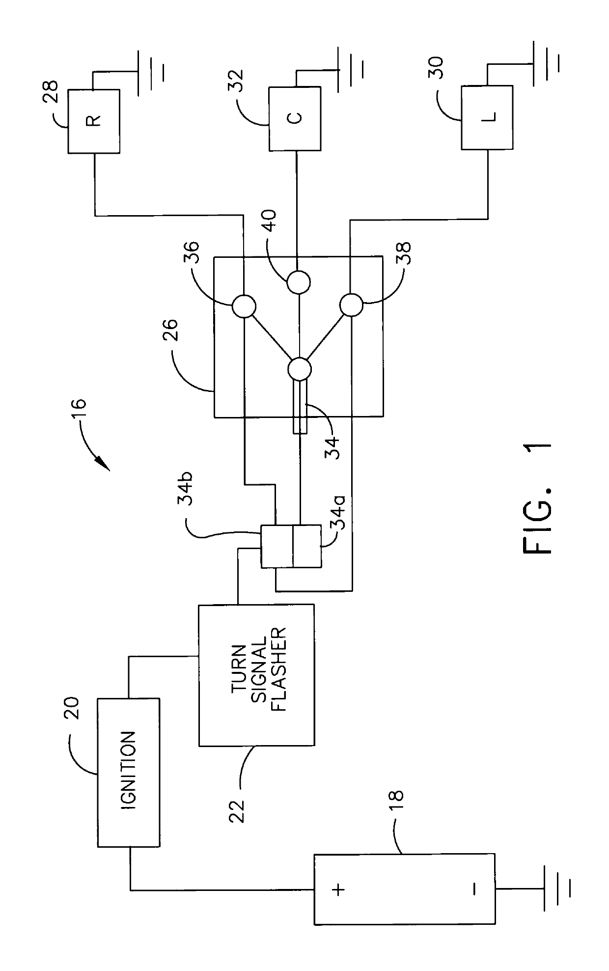
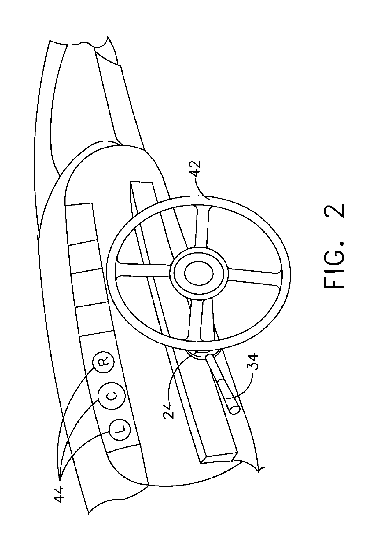
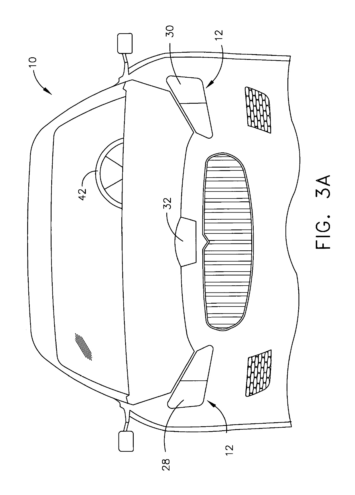
[0019]Directional indicators, or turn signals, in vehicles work either manually by a driver or autonomously by a computer by activating a lever or switch or indicator in a vehicle 10, such as is illustrated in FIGS. 3A and 3B. The directional intentions of a vehicle are indicated at the front and back of the vehicle 10 exterior, at light sources 12 and 14, respectively. As illustrated in the directional indicator circuit diagram 16 of FIG. 1, a directional signal is powered up via a power source 18 when the vehicle ignition 20 is turned on. The power source 18 can be any suitable power source, such as a grounded battery power source, a fuse panel, or a junction box, sufficient to transfer power. The power travels from the power source 18 into the thermal flasher 22 to the steering column 24 of the vehicle 10. From here, in accordance with the present invention, the power either stops in the directional indicator switch 26, or continues to the directional indicator lights 28, 30 and ...


PUM


Abstract

A vehicle directional indicator is provided for enhancing the safety and knowledge of all persons using roadways, including drivers, pedestrians, and bikers. Depending on the position applied to the directional indicator for a driver or driverless vehicle, power can be sent to the left turn signal light or the right turn signal light or the straight ahead signal light. These signal lights include indicator lights on the dashboard, as well as front and rear exterior indicator lights. The straight ahead directional indication is particularly useful at an intersection, where multiple vehicles and pedestrians are weighing the directional indicators of the other vehicles at the intersection, assured clear distances, oncoming traffic and multiple other traffic patterns, to provide the safest and most timely continued travel.

Description

FIELD OF THE INVENTION[0001]This invention relates generally to vehicle directional indicator signals, and more particularly, to a vehicle directional indicator signal that indicates a straight ahead direction incorporated into the left and right turn directional signals, to indicate a straight ahead directional intention of a human or robot driver or driverless vehicle.BACKGROUND OF THE INVENTION[0002]In automobiles now in use, a turn signal switch is installed within easy reach of the driver of the vehicle, on or around the steering wheel. When a driver intends to turn right or left, the driver moves the turn signal switch or lever, activating an exterior indicator light in the front and rear of the vehicle. This alerts both oncoming drivers and trailing driver, as well as pedestrians and cyclists and others using the roadways, of the intention of the driver. Turn signals warn other drivers of impending moves to minimize hazards and abrupt actions.[0003]With the rapidly advancing ...

Claims


Application Information

Patent Timeline
Patent Type & Authority Patents(United States)
IPC IPC(8): B60Q1/38B60Q3/10B60Q1/34B60R16/033B60Q1/50B60Q1/26
CPCB60Q1/2607B60Q1/38B60Q1/343B60Q1/346B60Q3/10B60Q1/50B60R16/033B60Q1/507
Inventor HAUSHALTER, ALEXA LEA
Owner HAUSHALTER ALEXA LEA
Why Eureka
Try Eureka