
Optimal load distributing system

a load distribution system and load distribution technology, applied in adaptive control, process and machine control, instruments, etc., can solve the problems of inability to use operation optimization, inability to set input parameters, and complicated optimization model construction, etc., to minimize the fuel cost and minimize the fuel cost.

Active Publication Date: 2009-11-05
KK TOSHIBA
View PDF4 Cites 15 Cited by
  • Summary
  • Abstract
  • Description
  • Claims
  • Application Information

AI Technical Summary

Benefits of technology

[0008]The present invention has been made in view of such circumstances, and an object of the present invention is to provide an operation schedule that minimizes the fuel cost that involves a minimum number of input parameters, is calculated offline, and is arranged taking into account the output distribution among a plurality of units that minimizes the fuel cost.
[0011]According to the present invention, since plant specification of each of the units forming the power plant are input, a load distribution among the units that minimizes the fuel cost can be calculated for the total output designated from the load dispatching office, and the power plant can be operated based on the load distribution in such a manner that the fuel cost is minimized.

Problems solved by technology

Occasionally, however, construction of the optimization model is too complicated, so that input parameters cannot be set, and the operation optimization cannot be used.

Method used


Image

  • Optimal load distributing system
  • Optimal load distributing system
  • Optimal load distributing system

Examples


embodiment 1

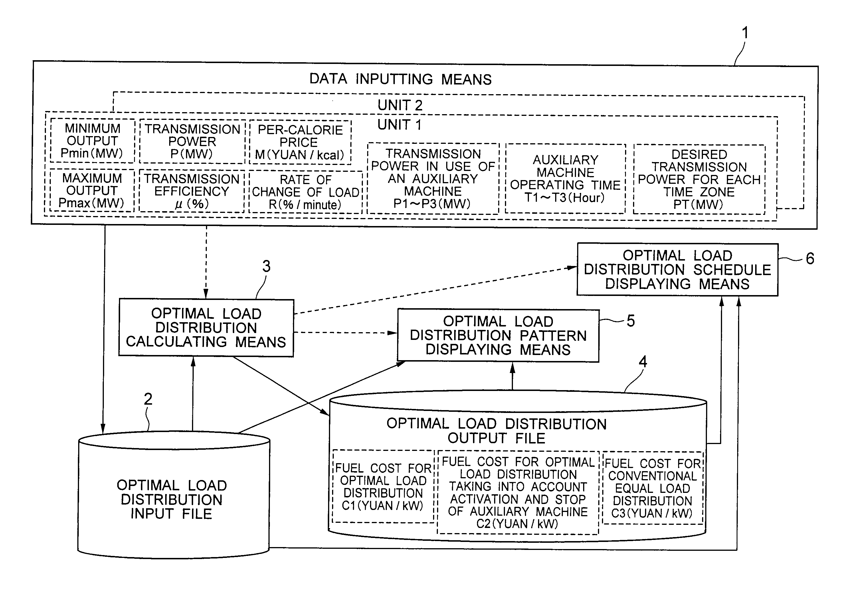
[0028]FIG. 1 is a diagram showing a configuration of an optimal load distributing system according to an embodiment 1 of the present invention. First, the configuration of the optimal load distributing system according to the embodiment 1 will be described with reference to FIG. 1. According to the embodiment 1, the optimal load distributing system has data inputting means 1 for inputting plant specifications of each unit (two units) required for optimal load distribution, an optimal load distribution input file 2 that stores data input via the data inputting means 1, optimal load distribution calculating means 3 that carries out an optimal load distribution calculation based on the data stored in the optimal load distribution input file 2, an optimal load distribution output file 4 that stores the result of the calculation carried out by the optimal load distribution calculating means 3, optimal load distribution pattern displaying means 5 that displays a sending-end characteristic...

embodiment 2

[0054]In the following, an embodiment 2 of the present invention will be described. The configuration of an optimal load distributing system of the embodiment 2 is the same as that of the embodiment 1 except that the data inputting means can deal with three or more units, and therefore, descriptions of the configuration will be omitted.

[0055]Next, an operation of the optimal load distributing system will be described. FIG. 2B shows an exemplary optimal load distribution calculation involved in the operation according to the embodiment 2. The input / output data items and the calculation methods are the same as in the embodiment 1 except for the number of units.

[0056]In the embodiment 2, it is supposed that optimal load distribution among three units (a first unit, a second unit and a third unit) is calculated. In the case where there are three or more units, those units are grouped into two virtual units. In the embodiment 2, the first and the second unit are grouped as a virtual N-th...

embodiment 3

[0065]In the following, an optimal load distributing system according to an embodiment 3 of the present invention will be described. The configuration of the optimal load distributing system of the embodiment 3 is the same as that of the embodiment 1, and therefore, descriptions of the configuration will be omitted.

[0066]Next, an operation of the optimal load distributing system will be described. The optimal load distribution pattern displaying means 5 in the embodiment 1 displays the following curves based on the data stored in the optimal load distribution input file 2 and the optimal load distribution output data calculated by the optimal load distribution calculating means 3.

[0067]

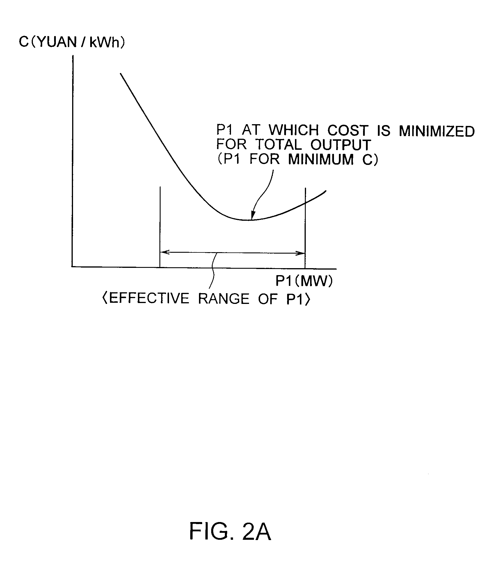
[0068](1) a sending-end efficiency characteristic curve and a fuel cost curve for each unit (shown in FIG. 3A)

[0069](2) a curve of the optimal load distributed to each unit versus the total output and a fuel cost curve for the total output (shown in FIG. 3B)

[0070](3) a fuel cost curve for conventional...


PUM


Abstract

To provide an operation schedule that minimizes the fuel cost that involves a minimum number of input parameters, is calculated offline, and is arranged taking into account the output distribution among a plurality of units that minimizes the fuel cost.An optimal load distributing system for managing an optimal load distribution of a total output of a power plant composed of a plurality of units among the plurality of units has: a data inputting part 1 that is used for inputting plant specifications of each unit required for optimal load distribution; an optimal load distribution input file 2 that stores data input via the data inputting part; an optimal load distribution calculating part 3 that carries out an optimal load distribution calculation based on data stored in the optimal load distribution input file; an optimal load distribution output file 4 that stores the result of the calculation carried out by the optimal load distribution calculating part; an optimal load distribution pattern displaying part 5 that displays a sending-end characteristic curve for each unit, a fuel cost curve for each unit, a curve of the load optimally distributed to each unit versus the total output, a fuel cost curve for the total output, and fuel cost curves for comparison between a conventional load distribution and the optimal load distribution based on data stored in the optimal load distribution output file and the optimal load distribution input file; and an optimal load distribution schedule displaying part 6 that displays a power transmission time schedule table, a power transmission time schedule curve, and a fuel cost comparison table for different operating schemes.

Description

BACKGROUND OF THE INVENTION[0001]1. Field of the Invention[0002]The present invention relates to an optimal load distributing system in a power plant. In particular, it relates to a system that carries out optimal load distribution taking the fuel cost into account.[0003]2. Related Art[0004]In general, a power plant is composed of a plurality of units, and the operational plan of each unit is determined according to the total output designated by the load dispatching office. According to the prior art, the way of distributing the load among the units to achieve the total output depends on the experience of the operator, and the power transmission cost is not always minimized.[0005]In recent years, electricity markets have been established, and power companies have been demanded to improve the operational efficiency. Thus, there is a demand for a feature that helps distribute the load among the units in such a manner that the transmission power cost for the total power designated by ...

Claims


Application Information

Patent Timeline
Patent Type & Authority Applications(United States)
IPC IPC(8): G05D17/00
CPCH02J3/00Y02E60/76Y04S40/22H02J2003/007H02J2203/20Y02B70/3225Y02E60/00Y04S20/222Y04S40/20
Inventor IWAMOTO, TETSUYAWATANABE, TSUNEO
Owner KK TOSHIBA
Learn More