Storage power supply system, storage device, and control thereof

a power supply system and storage technology, applied in emergency power supply arrangements, liquid/fluent solid measurement, instruments, etc., can solve the problems of inability to protect the power supply system, complex ups circuit, and inability to utilize the ups for general use, and achieve the effect of simple system configuration

Active Publication Date: 2009-11-05
BUFFALO CORP LTD
View PDF2 Cites 22 Cited by
  • Summary
  • Abstract
  • Description
  • Claims
  • Application Information

AI Technical Summary

Benefits of technology

[0009]The present invention discloses to enable with a simple system configuration the processing corresponding to a state in which backup power is supplied when the commercial power supply is interrupted even in a storage device in which the state in which backup power is supplied cannot be directly recognized from the uninterrupted power supply.

Problems solved by technology

For this reason, in a case where a large number of NAS are connected to a network and power from the UPS is supplied to these NAS, there are NAS that cannot input the signal indicating power supply interruption when the power supply interruption occurs and such NAS cannot be protected by shutting down the NAS during power supply interruption.
With the feature described in Japanese Patent Application Laid-open No. 2005-253243, because the UPS has to be provided with a power line network interface, the UPS circuit becomes complex and the UPS for general use cannot be utilized.

Method used


Image

  • Storage power supply system, storage device, and control thereof
  • Storage power supply system, storage device, and control thereof
  • Storage power supply system, storage device, and control thereof

Examples


modification examples

[0121](3) Other Modification Examples

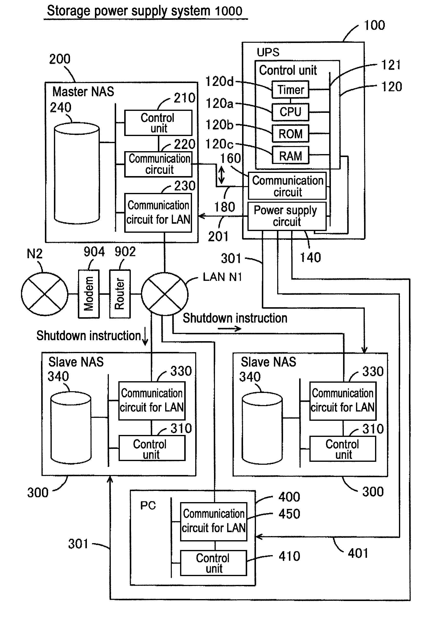
[0122]It is also possible that a slave NAS (second slave NAS) that is paired with a slave NAS (first slave NAS) be not connected to the internal network. In this case, the first slave NAS may generate a shutdown instruction (information corresponding to supply of backup power) that causes the execution of shutdown processing corresponding to a state in which backup power is supplied to the second slave NAS and may perform the shutdown processing on itself when a shutdown instruction (information corresponding to supply of backup power) is generated in the master NAS. The second slave NAS may perform the shutdown processing on itself when the shutdown instruction is generated in the first slave NAS. The storage device that executes the shutdown processing can also have a layered structure number of layers larger than that in the three-layer structure.

[0123]Furthermore, the master NAS and slave NAS may be connected by a special signal cable, for ex...


PUM


Abstract

The present invention discloses a storage power supply system includes a first storage device coupled with a network, a second storage device coupled with the network and an uninterrupted power supply. The uninterrupted power supply comprises a backup circuit that supplies backup power when commercial power supply is interrupted. The uninterrupted power supply comprises a power supply state signal generation circuit that generates a power supply state signal indicating a state of the power. The power supply state signal includes a backup state signal indicating a supply of backup power. The first storage device performs a self-processing corresponding to a state in which backup power is supplied when the backup state signal generated by the power supply state signal generation circuit is inputted. The second storage device performs a self-processing corresponding to a state in which backup power is supplied in response to the input of the backup state signal from the power supply state signal generation circuit to the first storage device.

Description

CROSS-REFERENCES TO RELATED APPLICATIONS[0001]This Application is a CONTINUATION application claiming the benefit of priority of the co-pending International Patent Application No. PCT / JP2008 / 050698 with an international filing date of 21 Jan. 2008 that designated the United States, which claims the benefit of priority of Japanese Patent Application No. 2007-012468, filed Jan. 23, 2007, the entire disclosures of all Applications are expressly incorporated by reference in their entirety herein.BACKGROUND OF THE INVENTION[0002]1. Field of the Invention[0003]The present invention relates to a storage power supply system in which power from an uninterrupted power supply is supplied to a storage device, a storage device constituting the storage power supply system, and control thereof.[0004]2. Description of Related Art[0005]In order to protect a network attached storage (NAS), power from an uninterrupted power supply (UPS) is supplied to the NAS. Because the supply time of backup power ...

Claims


Application Information

Patent Timeline
Patent Type & Authority Applications(United States)
IPC IPC(8): G06F1/26G06F1/28H02J9/00
CPCG06F1/30
Inventor SAITO, SHINSUKE
Owner BUFFALO CORP LTD
Why Eureka
Try Eureka