Crawler belt and master link for crawler belt

a crawler belt and master link technology, applied in the field of crawler belts, can solve the problems of increasing the production cost of the master link, affecting the performance of the crawler belt, and the failure of the track shoe mounting bolt, so as to facilitate the connection and disconnection of the crawler belt, and simplify the system configuration. , the effect of easy connection and disconnection

Active Publication Date: 2012-06-21
KOMATSU LTD
View PDF4 Cites 18 Cited by
  • Summary
  • Abstract
  • Description
  • Claims
  • Application Information

AI Technical Summary

Benefits of technology

[0061]In the crawler belt according to the first aspect of the invention, the master link is provided with the slit aperture which leads to the central through hole and to the second insertion hole, and the second bolt is screwed into the second screw hole so as to pass transversely across this slit aperture. Therefore, the clamping force generated by tightening the second bolt works on only the second coupling pin inserted into the second insertion hole that leads to the slit aperture. Since a proper clamping force can be applied to the second coupling pin inserted into the second insertion hole that leads to the slit aperture by controlling the tightening force for the second bolt, connection of the crawler belt can be easily performed.
[0062]In addition, since the second coupling pin can be easily extracted from the second insertion hole that leads to the slit aperture by releasing the tightening force for the second bolt, disconnection of the crawler belt can be easily performed.
[0063]Accordingly, the crawler belt according to the first aspect of the invention accomplishes easy connection and disconnection of the crawler belt through the operation of the second bolt that serves as a fastening device. In addition, the amount of tightening the fastening device can be adjusted by the spacer, and therefore a proper clamping force can be more readily and accurately applied to the coupling pin.
[0064]The configuration according to the second aspect of the invention eliminates the need for a special fastening device for narrowing the slit aperture, which leads to simplification of the system configuration.
[0065]The master link according to the third aspect of the invention enables it to easily perform connection and disconnection of the crawler belt.
[0066]In the crawler belt according to the fourth aspect of the invention, the first master link is provided with the first slit aperture that leads to only the insertion hole located at the other end of the first master link, and the second master link is provided with the second slit aperture that leads to only the insertion hole located at the one end of the second master link. Therefore, the clamping force generated by tightening the first fastening device and the clamping force generated by tightening the second fastening device work on the second coupling pin alone.

Problems solved by technology

However, the removal and insertion of the master pin requires a press machine and involves a lot of trouble, which causes difficulties in mounting and dismounting of the crawler belt.
As a result, there arises the problem that the production cost of the master link increases.
In addition, since the master link is configured to be set up by tightly fastening the two half links with the track shoe mounting bolt, there is a risk that the track shoe mounting bolt fractures, for example, when an impactive load is imposed on the master link.

Method used


Image

  • Crawler belt and master link for crawler belt
  • Crawler belt and master link for crawler belt
  • Crawler belt and master link for crawler belt

Examples


first embodiment

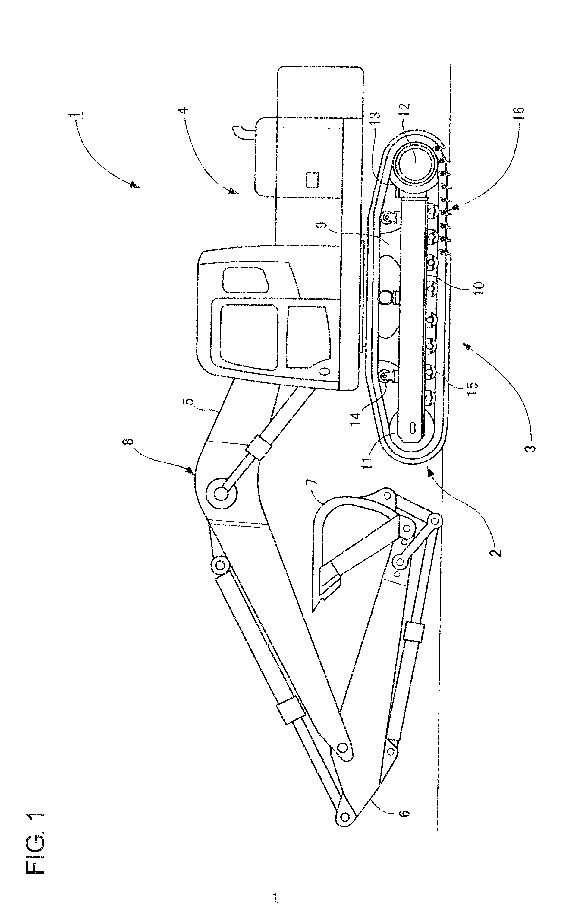
[0081]FIG. 1 shows a side view of a hydraulic excavator equipped with a crawler belt according to a first embodiment of the invention.

[0082](Outline of Hydraulic Excavator)

[0083]FIG. 1 shows a hydraulic excavator 1 that is equipped with lower machinery 3 having a crawler track unit 2 and a revolving superstructure 4 mounted on the lower machinery 3 so as to be freely revolvable.

[0084]Mounted to the center of the front part of the revolving superstructure 4 is a work implement 8 to which a boom 5, an arm 6 and a bucket 7 are connected such that they are freely pivotable relative to each other. Operations such as digging are performed through bending and hoisting of the work implement 8.

[0085](Outline of Crawler Track Unit of Hydraulic Excavator)

[0086]The crawler track unit 2 has crawler frames 10 (only the left crawler frame is shown) which are located on the opposed sides, respectively, of a center frame 9 of the lower machinery 3, extending in a longitudinal direction.

[0087]In each...

second embodiment

[0153]FIG. 4 shows a side view of a bulldozer equipped with a crawler belt according to a second embodiment of the invention.

[0154](Outline of Bulldozer)

[0155]FIG. 4 shows a bulldozer 51 which has a vehicle body 52, crawler travel units (only left crawler travel unit is shown) 53 disposed on the right and left sides, respectively, of the vehicle body 52, a blade (front work implement) 54 located in front of the vehicle body 52, and a ripper (rear work implement) 55 located behind the vehicle body 52. The bulldozer 51 is configured to perform dozing and carrying by the blade 54 and crushing and digging by the ripper 55.

[0156](Outline of Crawler Travel Unit of Bulldozer)

[0157]Each crawler travel unit 53 has a track frame 56 that constitutes its framework. The track frame 56 is disposed in front of a sprocket 57 so as to extend in a longitudinal direction, the sprocket 57 serving as a driving wheel and being supported by the rear part of the vehicle body 52. In front of the track frame...


PUM


Abstract

A crawler belt and a master link for use in the crawler belt enable easy connection and disconnection of the crawler belt. The crawler belt has a track chain, in which a plurality of regular links are pivotally connected at their ends, the master link for connecting the ends of the track chain to form the crawler belt into a loop, and track shoes attached to the regular links and the master link respectively. The crawler belt has a slit aperture which leads only to a pin insertion hole formed at the other end of the master link and is configured such that a clamping force, generated by tightening a master bolt that imparts a tightening force to the master link to narrow the slit aperture, is allowed to work on only the regular pin inserted into a pin insertion hole leading to the slit aperture.

Description

TECHNICAL FIELD[0001]The invention relates to a crawler belt for use in a work vehicle such as hydraulic excavators and bulldozers and to a master link that is used for forming a crawler belt into an endless loop.BACKGROUND ART[0002]Generally, a crawler belt provided for a work vehicle of this type encircles an idler tumbler (idler) and a driving wheel (sprocket), forming an elliptical shape to provide an endless track between these idler tumbler and driving wheel. The driving wheel is rotatively driven to cause the crawler belt to rotate about a path between the idler tumbler and the driving wheel so that the work vehicle is stably propelled over the irregular terrain or the like.[0003]The crawler belt is composed of a track chain in which a plurality of regular links are rotatably connected to each other at their ends; track shoes attached to the regular links respectively; and a coupling device for connecting the opposed ends of the track chain to form the crawler belt into a loo...

Claims


Application Information

Patent Timeline
Patent Type & Authority Applications(United States)
IPC IPC(8): B62D55/205B62D55/21
CPCB62D55/092B62D55/213B62D55/21B62D55/08B62D55/18B62D55/205
Inventor TSUBAKI, TOMOYUKIITOU, DAIJIROUHISAMATSU, KENICHIMARUMOTO, SHIGETO
Owner KOMATSU LTD
Why Eureka
Try Eureka