
Diverter assembly for use in holding shower head and shower nozzle

a technology for shower heads and shower nozzles, which is applied in the direction of multiple way valves, mechanical devices, transportation and packaging, etc., can solve the problems of shower nozzles falling off, shower nozzles secured in the attaching device, and nothing between the attaching device and the partition for securing the attaching devi

Inactive Publication Date: 2009-11-12
GLOBE UNION INDAL
View PDF7 Cites 27 Cited by
  • Summary
  • Abstract
  • Description
  • Claims
  • Application Information

AI Technical Summary

Benefits of technology

[0010]The primary object of the present invention is to solve the above-mentioned issues and to provide a diverter assembly for holding a handheld shower nozzle, and for controlling the amount of water to flow out through either or both of a shower head and the shower nozzle steplessly.
[0011]The secondary object of the present invention is to provide a multi-position movable body for securing the shower nozzle.

Problems solved by technology

Although the above-mentioned controlling technique of the three valve stem positions satisfies basic needs of users, when the valve stem switches to the position to have the water flow out through both of the outlet ports, that is, when the water flows out through both of the shower head and the shower nozzle, users can not further adjust the amount of the water flowing out through both of the shower head and the shower nozzle.
However, there is nothing between the attaching device and the partition for securing the attaching device, and the securing of the attaching device comes from the friction among the follower, the attaching device and the partition.
If the screw for securing the follower and the attaching device is loosen, or after being used for a long time, a wearing issue occurs among the follower, the attaching device and the partition such that the attaching device loses securing capability, resulting in the falling of the shower nozzle secured in the attaching device.
The falling of the shower nozzle can result in damaging of the shower nozzle or other appliance, or more seriously, hurt users thereof.

Method used


Image

  • Diverter assembly for use in holding shower head and shower nozzle
  • Diverter assembly for use in holding shower head and shower nozzle
  • Diverter assembly for use in holding shower head and shower nozzle

Examples


Embodiment Construction

[0023]Refer to FIG. 1 to FIG. 7, which shows a preferred embodiment according to the present invention.

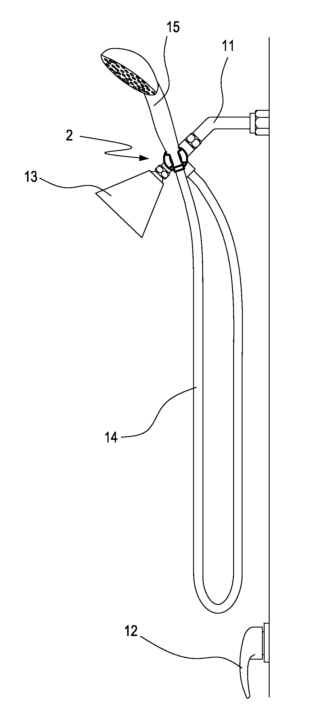
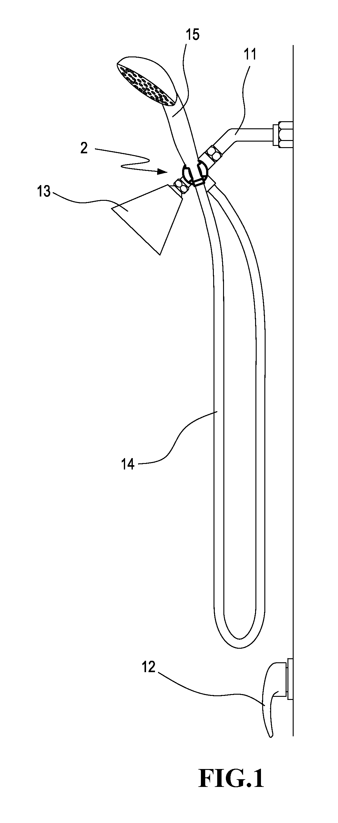
[0024]Refer to FIG. 1, which is a schematic view of a shower appliance according to the present invention. A shower appliance usually has a water outlet tube 11 protruding on top of a wall. The water flowing out of the water outlet tube 11 is controlled by a switch 12 disposed on bottom of the wall. The diverter assembly 2 of the present invention is integrated with the water outlet tube 11, respectively communicated with a shower head 13 and communicated with a handheld shower nozzle 15 by a hose 14.

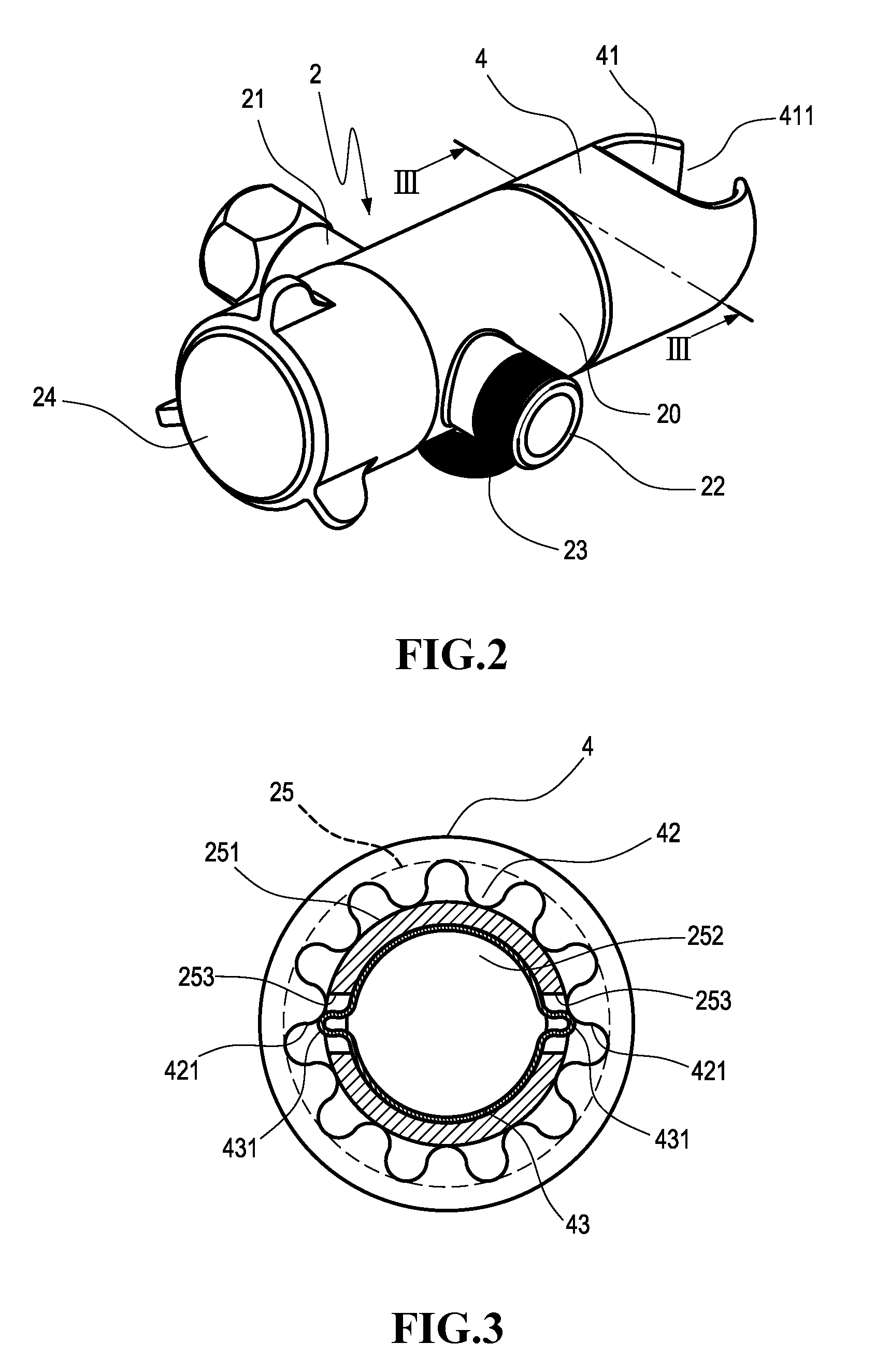
[0025]Refer to FIG. 2, which is a perspective view of the present invention. The diverter assembly 2 of the present invention has a hollow main body 20. The main body 20 has a water inlet tube 21, a first water outlet tube 22 and a second water outlet tube 23. A knob 24 is pivotally disposed at one end of the main body 20. The knob 24 rotates in accordance with a valve device 3 (referr...


PUM


Abstract

A diverter assembly includes a main body, a valve device and a movable body. The main body is hollow and has a water inlet tube and two water outlet tubes. One of the two water outlet tubes is communicated through a hose to a shower nozzle. The valve device is disposed on the main body and has a valve capable of linearly moving back and forth for steplessly communicating the water inlet tube with either or both of the water outlet tubes. The movable body is pivotally disposed at one end of the main body, and has a hole for the shower nozzle to be inserted in. Thereby, the diverter assembly can steplessly adjust the valve position for controlling the water to flow out from either or both of the water outlet tubes.

Description

BACKGROUND OF THE INVENTION[0001]1. Field of Invention[0002]The present invention relates to a diverter assembly for shower, and more particularly to a diverter assembly for holding a shower nozzle, and for controlling the amount of water to flow out through either or both of a shower head and a shower nozzle steplessly.[0003]2. Related Art[0004]Typical American shower appliances include a shower head fixed on a wall and a shower nozzle for a user to hold, and a diverter is disposed between the shower head and the shower nozzle for controlling the water to flow out through either or both of the shower head and the nozzle.[0005]U.S. Pat. No. 7,299,510 discloses a holder device for a shower head and a shower nozzle as described above. The holder device includes an inlet and two outlet ports. A knob is pivotally disposed at one end of the holder device to operate a valve stem disposed inside the holder device for controlling the water flowing directions. An attaching device is disposed...

Claims


Application Information

Patent Timeline
Patent Type & Authority Applications(United States)
IPC IPC(8): A47K3/28B05B1/16B05B15/06F16K11/00
CPCE03C1/0408F16K11/0445E03C2201/30Y10T137/698Y10T137/86815
Inventor HSU, WEI-MIENLI, CHUN-HUNG
Owner GLOBE UNION INDAL
Learn More