

Dynamic Window Jamb Channel Block
- Summary
- Abstract
- Description
- Claims
- Application Information
AI Technical Summary
Benefits of technology
Problems solved by technology
Method used
Image

Examples
Embodiment Construction
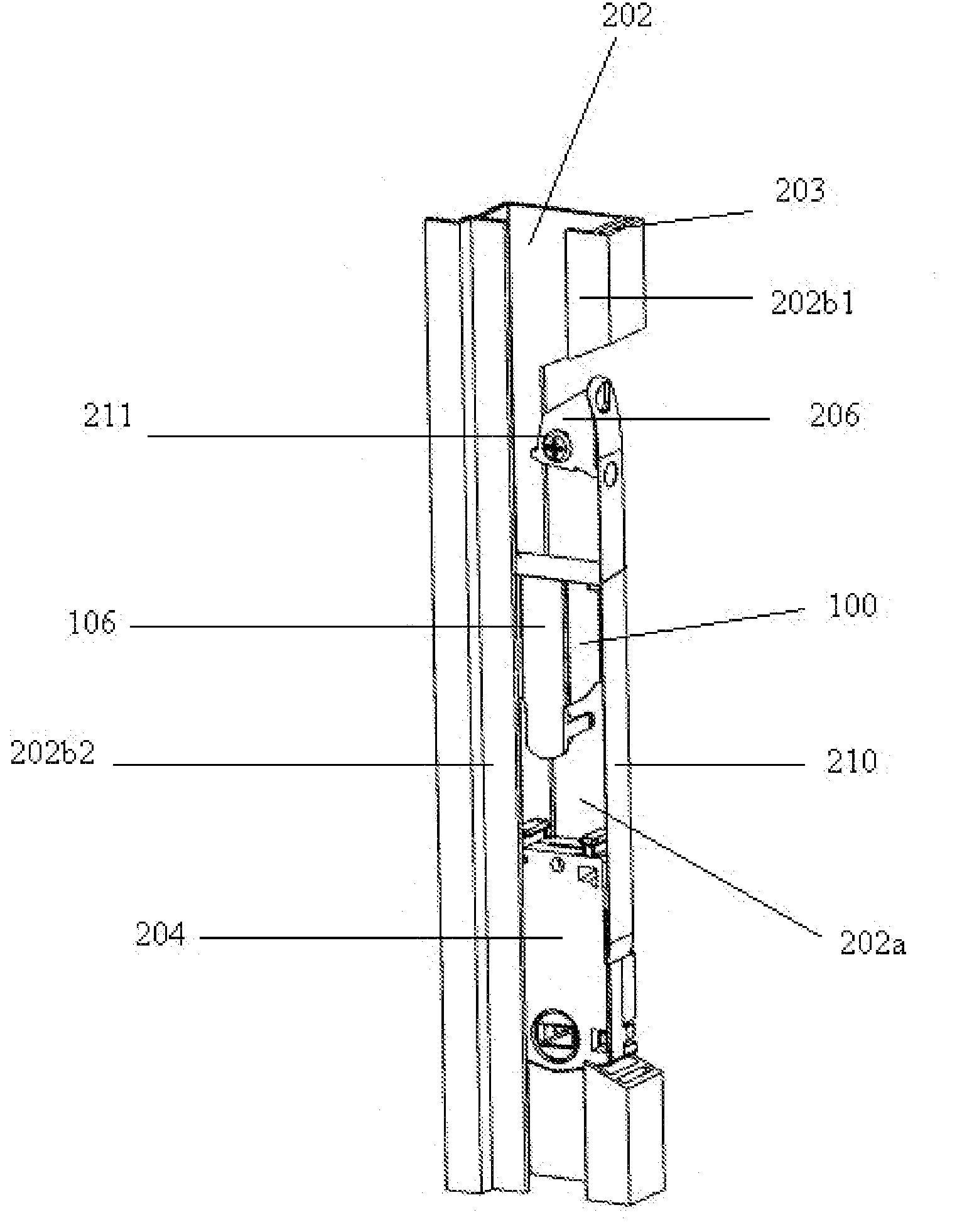
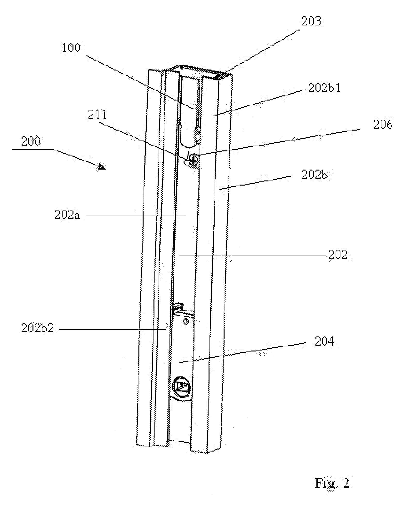
[0015]Referring first to FIG. 2, what is shown is a cut away of the jamb section 200 of a window frame (not fully shown). The jamb 200 contains a channel, known as a jamb channel 202. The jamb channel 202 provides the route through which a carrier travels with the vertical movement of the sash (not shown). The presently indicated carrier is a curl spring carrier 204, which will be shown in more detail in subsequent figures.
[0016]With respect to curl spring carriers, such as 204, an elongated spring is coiled within the body of the curl spring carrier 204. The end of the spring which extends outward from the body of the carrier is secured at a specific location in the jamb channel 202 by a mounting bracket 206 (best shown in FIG. 4). With one end of the spring secured to the wall of the jamb channel 202, the curl spring carrier 204 rides up and down the jamb channel 202 with the movement of the sash.
[0017]The jamb channel 202 must be large enough to accommodate the dimensions of the ...
PUM
 Abstract
Description
Claims
Application Information