Tempered glass cooling device

A cooling device and a technology for tempered glass, which are applied in glass tempering, glass transportation equipment, glass manufacturing equipment, etc., can solve the problems of insufficient high-pressure cold air, insufficient cooling, waste of high-pressure cold air, etc., to reduce the waste of cold air, The effect of increasing the amount

Pending Publication Date: 2022-07-29
晏文旋
View PDF0 Cites 0 Cited by
  • Summary
  • Abstract
  • Description
  • Claims
  • Application Information

AI Technical Summary

Problems solved by technology

[0003] Based on the existing cooling device, there is a problem of uneven cooling of tempered glass. When the glass to be cooled is wide, it will cause insufficient high-pressure cold air, resulting in ins

Method used


Image

  • Tempered glass cooling device
  • Tempered glass cooling device
  • Tempered glass cooling device

Examples


Example Embodiment

[0030] Example 1

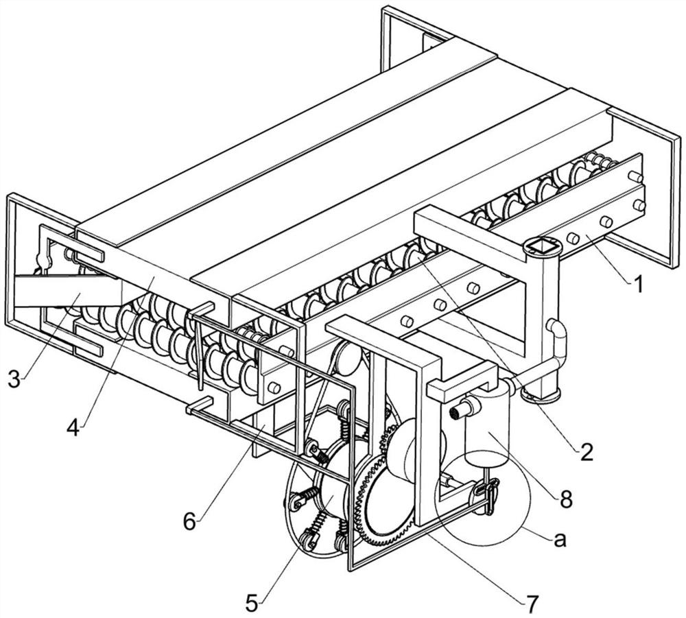
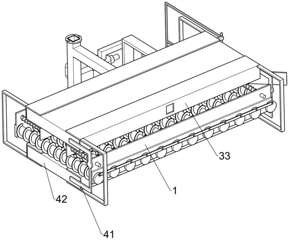
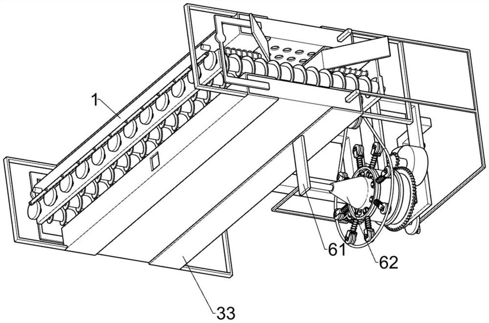
[0031] A tempered glass cooling device, such as Figure 1-9 As shown, it includes a long mounting plate 1, a conveying part 2, a glass width detecting part 3, an exhaust part 4, a driving speed adjusting part 5 and an adjusting part 6, the long mounting plate 1 is provided with a conveying part 2, and the conveying part The function of 2 is to transport the glass. The conveying part 2 is provided with a glass width detection part 3 and an exhaust part 4. The glass width detection part 3 can control the displacement of cooling air according to the width of the glass, and the exhaust part 4 can discharge The cold air cools the glass, the glass width detection part 3 is connected with the exhaust part 4, the long mounting plate 1 is provided with a driving speed adjusting part 5, and the driving speed adjusting part 5 can adjust the conveying speed of the glass according to the width of the glass. For adjustment, the driving speed adjusting member 5 is connect...

Example Embodiment

[0032] Example 2

[0033] On the basis of Example 1, as Figure 1-9 As shown, the conveying member 2 includes a conveying roller 21, a rotating disc 22 and a connecting rod 23. A plurality of conveying rollers 21 are rotatably mounted on the long mounting plate 1. The conveying roller 21 can transmit the glass. One end of the conveying roller 21 Several rotating disks 22 are fixedly installed, and connecting rods 23 are rotatably connected to the rotating disks 22 .

[0034]The glass width detection component 3 includes an inclined surface driven plate 31, a compression spring 32, a limit frame 33 and a U-shaped link 34. Two inclined surface driven plates 31 are slidably mounted on the two long mounting plates 1 and are symmetrical Installation, a compression spring 32 is connected between the inclined surface driven plate 31 and the long installation plate 1, a limit frame 33 is fixedly installed on the inclined surface driven plate 31, and a U-shaped connecting rod 34 is we...

Example Embodiment

[0036] Example 3

[0037] On the basis of Example 2, as Figure 1-9 As shown, the drive speed adjusting part 5 includes an L-shaped support plate 51, a servo motor 52, a drive gear 53, a support strip 54, a rotating frame 55, a ring gear 56, a fixed ring 57, a movable strut 58 with a pulley, and a return spring 59. Friction support wheel 510, pulley 511 and elastic belt 512, L-shaped support plate 51 is fixedly installed on the long mounting plate 1, servo motor 52 is fixedly installed on the L-shaped support plate 51, and the output shaft of the servo motor 52 is fixed on A drive gear 53 is installed, a support strip 54 is fixedly installed on the L-shaped support plate 51, a rotating frame 55 is rotatably installed on the support strip 54, and a ring gear is fixedly installed on the end of the rotating frame 55 away from the long mounting plate 1 56. The driving gear 53 is located above the ring gear 56, and the ring gear 56 meshes with the driving gear 53. The rotation of ...


PUM


Abstract

The invention relates to the technical field of glass cooling, in particular to a tempered glass cooling device. The tempered glass cooling device convenient to adjust is provided. A tempered glass cooling device comprises a long mounting plate, a conveying component, a glass width detection component, an exhaust component and the like. The long mounting plate is provided with a conveying part, the conveying part is provided with a glass width detection part and an exhaust part, the glass width detection part is connected with the exhaust part, the long mounting plate is provided with a driving speed adjusting part, and the driving speed adjusting part is connected with the conveying part. When wide glass is cooled, the limiting frame does not block the area of the air guide holes in the square frame to be enlarged, so that the wide glass can be comprehensively cooled, when narrow glass is cooled, the narrow glass makes contact with the bevel driven plate, the limiting frame does not block the area of the air guide holes in the square frame to be small, and therefore the narrow glass can be fully cooled. Therefore, the effect of reducing waste of cold air can be achieved.

Description

technical field [0001] The invention relates to the technical field of glass cooling, in particular to a tempered glass cooling device. Background technique [0002] Tempered glass is glass with compressive stress on the surface, which has the advantages of safe use, high temperature resistance and high toughness. The market has various specifications for tempered glass and has a wide range of applications. At present, the processing technology of tempered glass cooling is mainly to place ordinary flat glass in a heating furnace and heat it until the glass softens, then remove the glass from the heating furnace, and then use an external multi-head nozzle device to blow high-pressure cold air to both sides of the glass. The method is easy to make the tempered glass cool unevenly, resulting in uneven stress distribution inside the glass. When the glass to be cooled is wider, it will cause insufficient high-pressure cold air, resulting in insufficient cooling. When the glass t...

Claims


Application Information

Patent Timeline
IPC IPC(8): C03B27/04C03B35/16
CPCC03B27/0404C03B27/044C03B35/162C03B35/166
Inventor 晏文旋
Owner 晏文旋
Why Eureka
Try Eureka