

Reactive in-flow control device for subterranean wellbores
a control device and subterranean technology, applied in the direction of drilling pipes, drilling casings, borehole/well accessories, etc., can solve the problems of reducing the amount and quality of produced oil, unsatisfactory conditions,
- Summary
- Abstract
- Description
- Claims
- Application Information
AI Technical Summary
Benefits of technology
Problems solved by technology
Method used
Image

Examples
Embodiment Construction
[0018]The present disclosure relates to devices and methods for controlling production of a hydrocarbon producing well. The present disclosure is susceptible to embodiments of different forms. There are shown in the drawings, and herein will be described in detail, specific embodiments of the present disclosure with the understanding that the present disclosure is to be considered an exemplification of the principles of the disclosure, and is not intended to limit the disclosure to that illustrated and described herein.
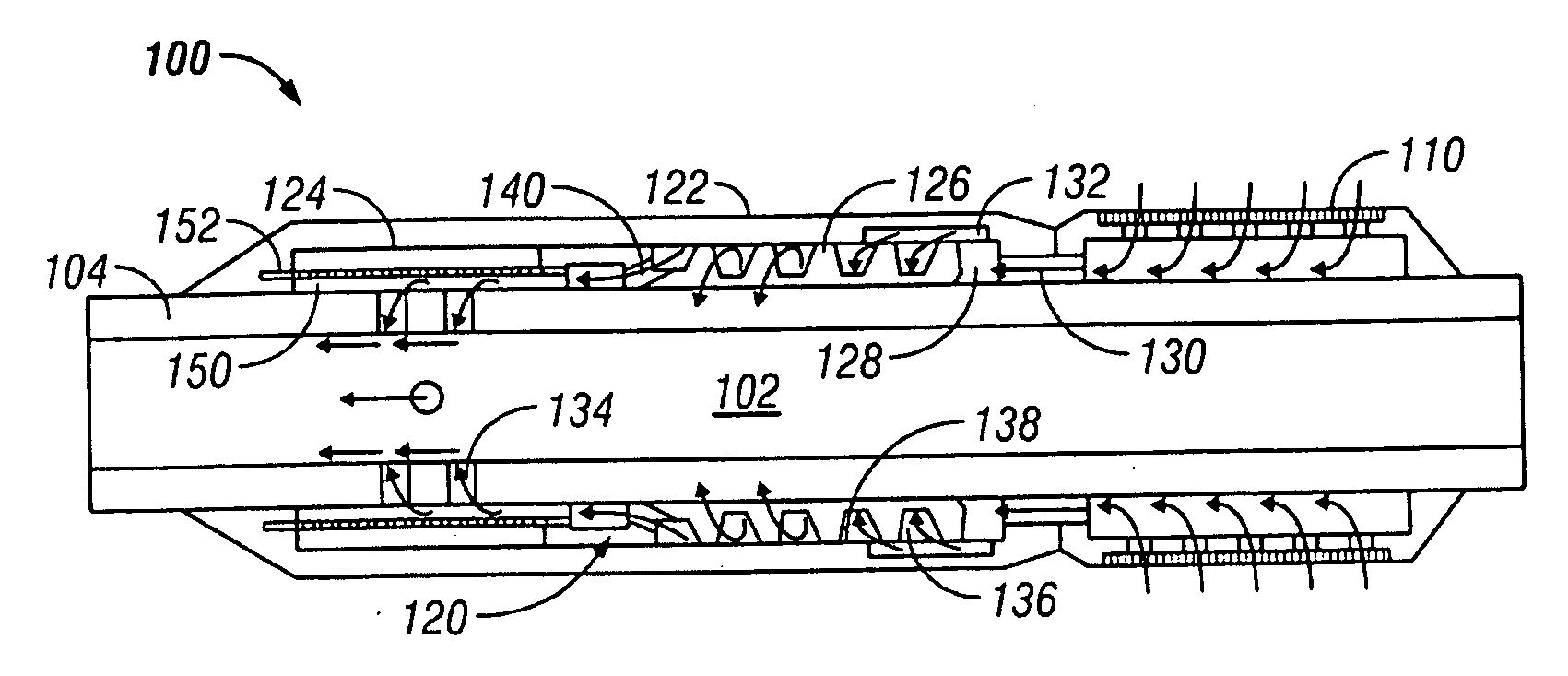
[0019]In aspects, in-flow of water into a wellbore tubular of an oil well is controlled, at least in part using a reactive actuator that can interact with one or more components in fluids produced from an underground formation. The media interaction may be of any kind known to be useful to move, pressurize, push, displace or otherwise actuate a given device.
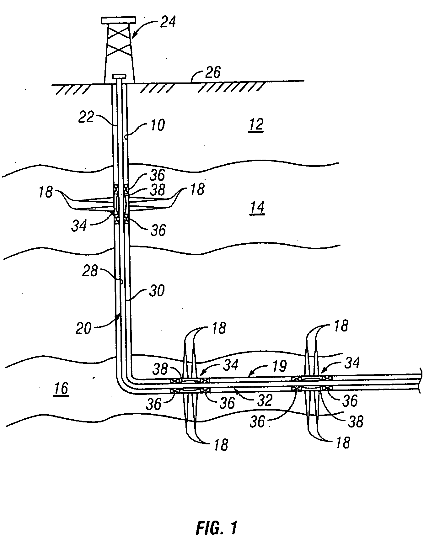
[0020]Referring initially to FIG. 1, there is shown an exemplary wellbore 10 that has been drilled through the e...
PUM
 Abstract
Description
Claims
Application Information