

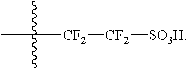
Polyelectrolyte membranes comprised of blends of pfsa and sulfonated pfcb polymers
a polyelectrolyte and polymer technology, applied in the field of polymer electrolyte and fuel cells, can solve the problems of excess membrane shrinkage, water swelling of random copolymers, and lack of mechanical robustness of random copolymer membranes
- Summary
- Abstract
- Description
- Claims
- Application Information
AI Technical Summary
Benefits of technology
Problems solved by technology
Method used
Image

Examples
Embodiment Construction
)
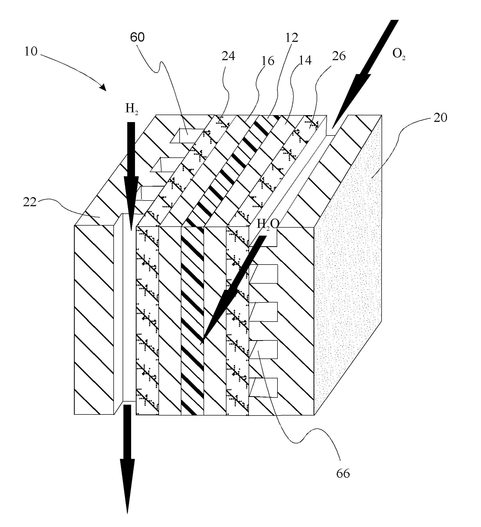
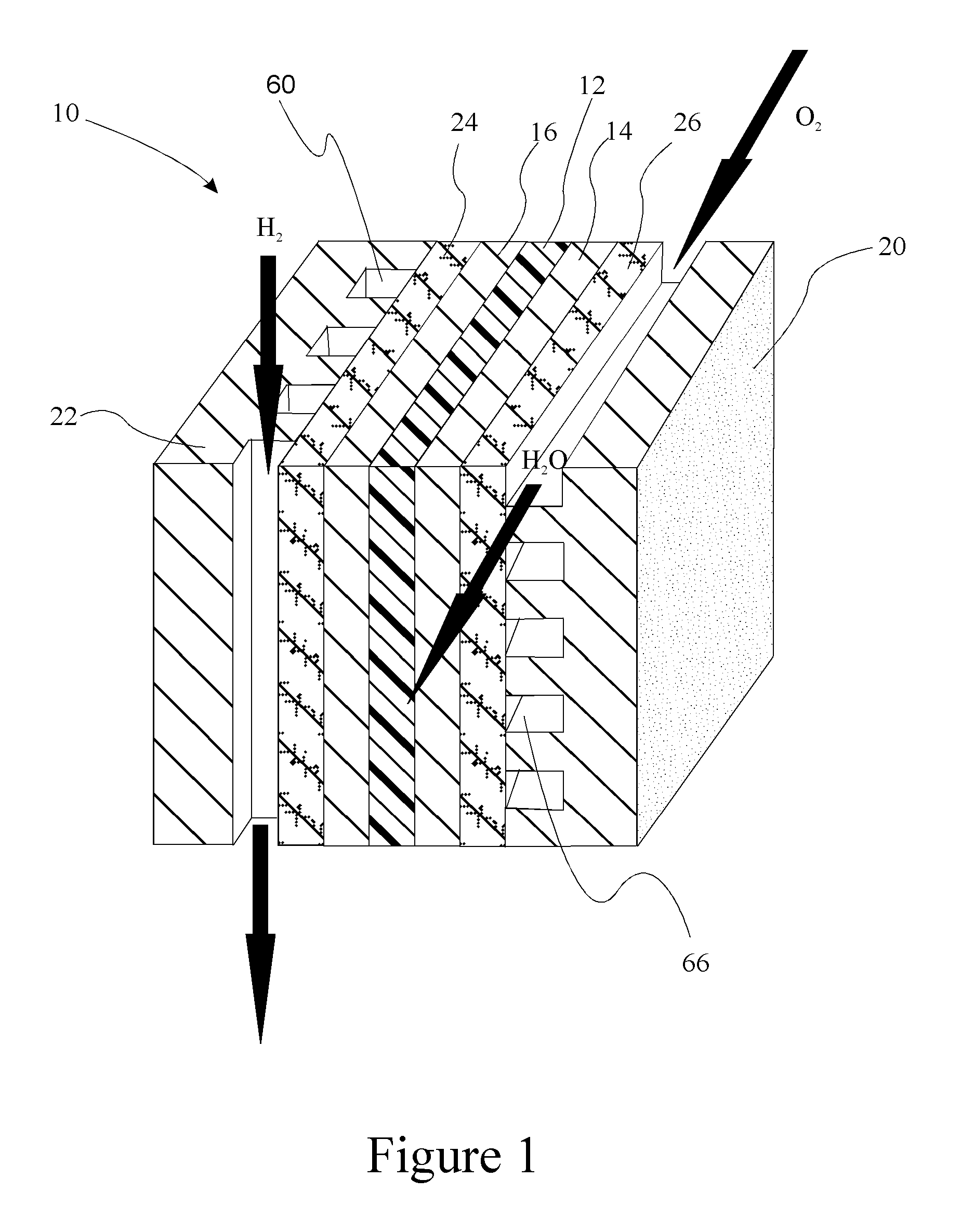
[0008]Reference will now be made in detail to presently preferred compositions, embodiments and methods of the present invention, which constitute the best modes of practicing the invention presently known to the inventors. The Figures are not necessarily to scale. However, it is to be understood that the disclosed embodiments are merely exemplary of the invention that may be embodied in various and alternative forms. Therefore, specific details disclosed herein are not to be interpreted as limiting, but merely as a representative basis for any aspect of the invention and / or as a representative basis for teaching one skilled in the art to variously employ the present invention.
[0009]Except in the examples, or where otherwise expressly indicated, all numerical quantities in this description indicating amounts of material or conditions of reaction and / or use are to be understood as modified by the word “about” in describing the broadest scope of the invention. Practice within the num...
PUM
| Property | Measurement | Unit |
|---|---|---|
| weight percent | aaaaa | aaaaa |
| weight percent | aaaaa | aaaaa |
| weight percent | aaaaa | aaaaa |
Abstract
Description
Claims
Application Information