Method and device for driving an array of light sources

a technology of light source and array, applied in the field of color illumination, can solve the problems of not being able to achieve the effect of simple and cost-effective solutions, and achieve the effect of avoiding the formation of a single device and reducing the number of devices

Inactive Publication Date: 2009-11-12
SIGNIFY HLDG BV
View PDF10 Cites 53 Cited by
  • Summary
  • Abstract
  • Description
  • Claims
  • Application Information

AI Technical Summary

Benefits of technology

[0010]In a system proposed by the present invention, the command signals are much simpler and control the respective LEDs directly. A command signal is implemented as a signal within a small frequency band, which signal is either present or absent. For different LEDs, different frequency bands are used. Each spot comprises filters corresponding to the respective frequency bands. A LED is directly controlled with the output signal of such filter: presence or absence of the signal means ON or OFF of the LED, so the duty cycle control of the LEDs is directly controlled by the central controller through duty cycle control of the command signals.

Problems solved by technology

Although this system does implement a central control, indeed, it is nevertheless rather complicated and costly in that each spot needs to have an intelligent device (such as a microprocessor) for receiving, decoding and processing the coded instructions.

Method used


Image

  • Method and device for driving an array of light sources
  • Method and device for driving an array of light sources
  • Method and device for driving an array of light sources

Examples


Embodiment Construction

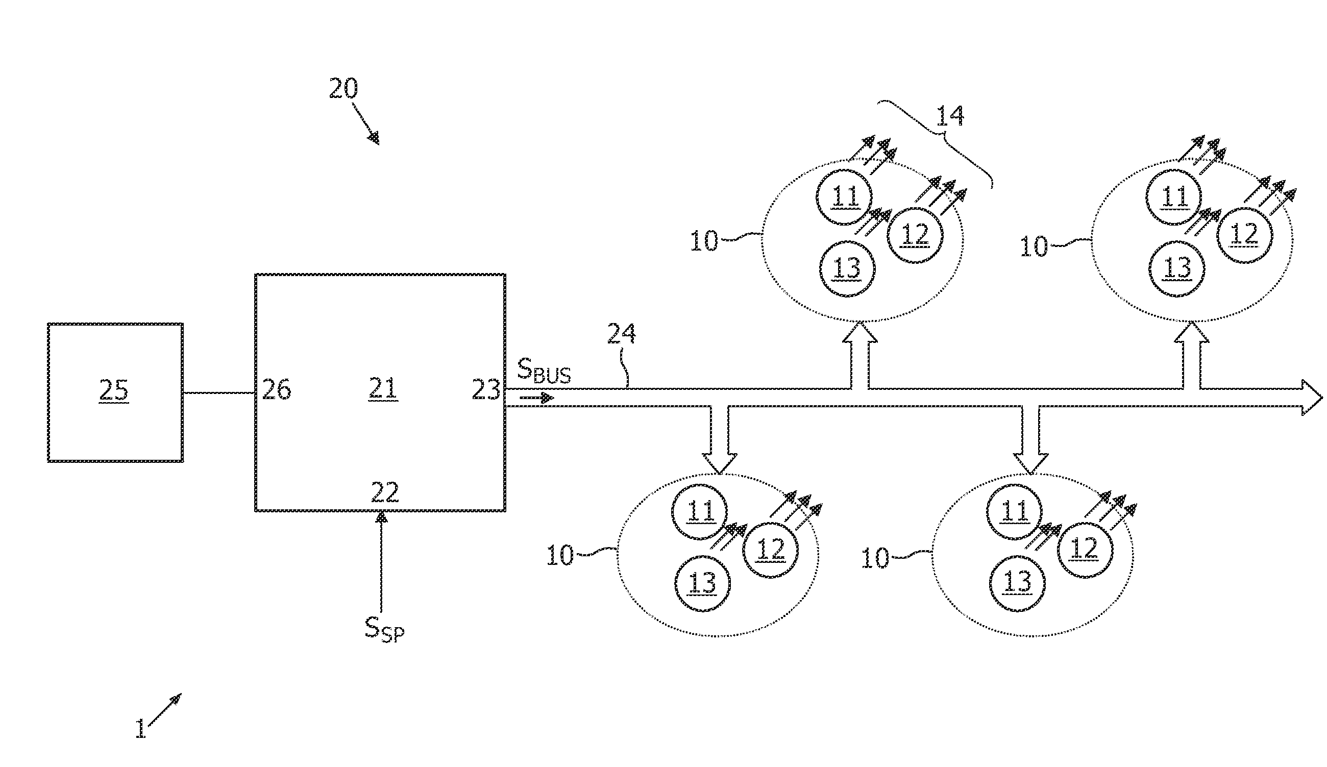
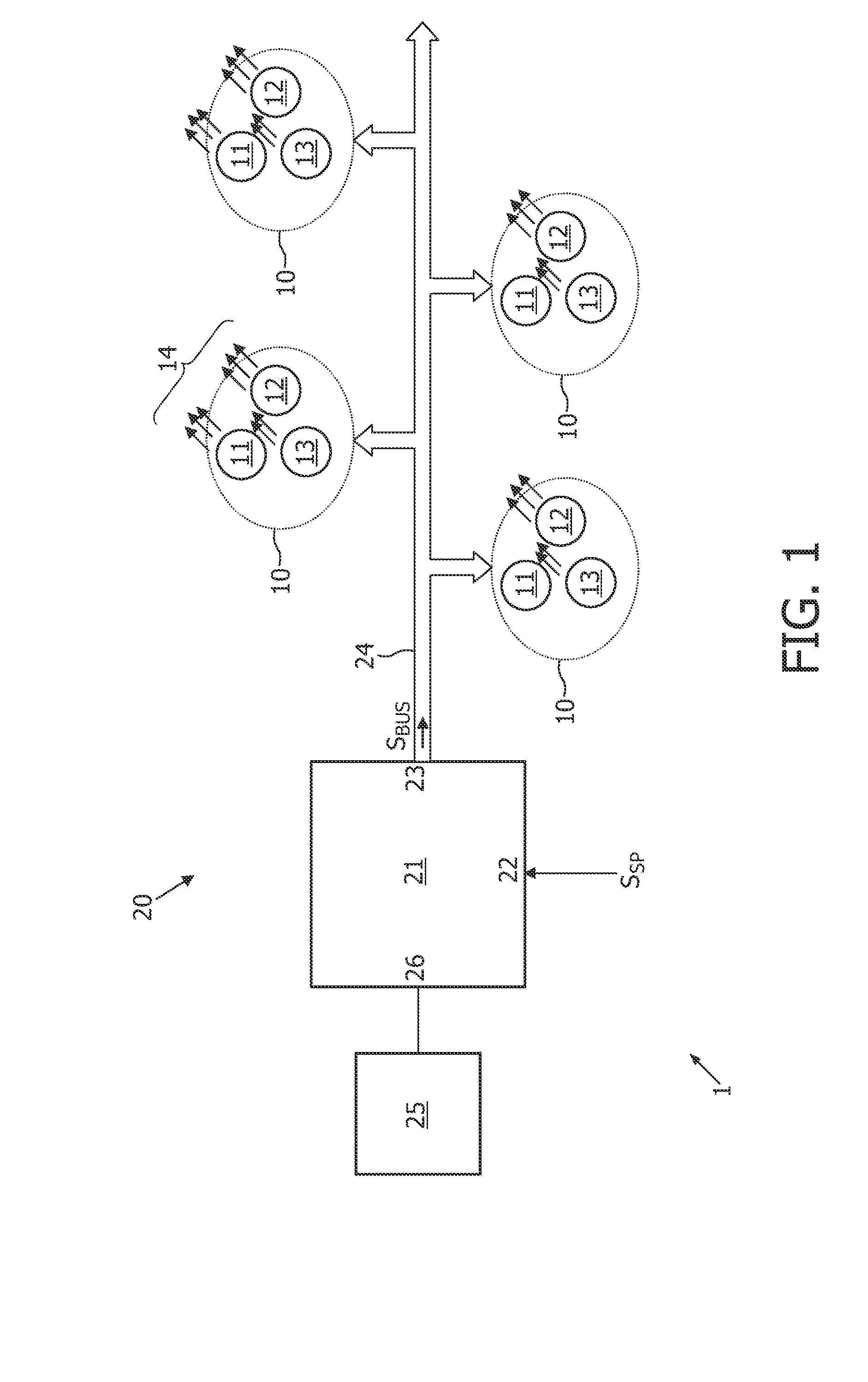
[0017]FIG. 1 schematically shows an illumination system 1, comprising a plurality of light source assemblies 10 and a control system 20. The Fig. shows four light source assemblies 10, but the number of light source assemblies may be three or less or may be five or more. In the following, a light source assembly will briefly be termed “spot”.

[0018]Each spot 10 comprises a plurality of primary light sources 11, 12, 13. The Fig. shows three primary light sources per spot, but the number of primary light sources may be more than three. In a preferred embodiment, the primary light sources are constituted by LEDs, although other types of light sources are also possible. Each primary light source may be constituted by one single LED (or other type of light source), but a primary light source may also be constituted by a plurality of LEDs (or other type of light source) connected in series and / or in parallel to increase the light output. The primary light sources 11, 12, 13 of one spot are...


PUM


Abstract

An illumination system (1) comprises a plurality of light source assemblies (10) and a common controller (21). Each light source assembly (10) comprises a plurality of individually controllable light sources (11, 12, 13) for generating light of mutually different colors. The controller is designed to generate a plurality of switched frequency signals (SF1, SF2, SF3) for the respective light sources, with a frequency within a relatively small frequency band, the different frequency signals (SF1, SF2, SF3) having mutually different frequencies (f1, f2, f3). In each light source assembly, each light source is responsive to a respective one of said switched frequency signals (SF1, SF2, SF3), the light source being ON for as long as the respective switched frequency signal is zero and being OFF for as long as the respective switched frequency signal has the respective frequency.

Description

FIELD OF THE INVENTION[0001]The present invention relates in general to the field of color illumination. More particularly, the present invention relates to an illumination device comprising a plurality of light sources, of which the color and the luminance level is controllable. In the following explanation, it will be assumed that each light source is implemented as a LED, but the present invention can also be practiced with other types of light sources, for instance TL lamps, halogen lamps, etc.BACKGROUND OF THE INVENTION[0002]Generally speaking, there is a desire for illumination devices that are capable of generating light with a variable light intensity (dimming) and variable color. As should be clear to a person skilled in the art and therefore needs no elaborate explanation, it is possible to generate light of all possible colors in a large portion of the color gamut with an arrangement that comprises three primary LEDs generating light of mutually different colors. In a typ...

Claims


Application Information

Patent Timeline
Patent Type & Authority Applications(United States)
IPC IPC(8): H05B37/02H05B44/00
CPCH02J13/0003H05B33/0818H05B33/0842Y04S20/18H05B37/0263Y02B20/346Y02B90/228H05B33/0857H05B47/185H05B45/20H05B45/305H05B45/10H05B45/3725Y02B20/30Y02B90/20Y04S20/00H05B45/37H05B47/155
Inventor VAN ERP, JOSEPHUS ADRIANUS MARIA
Owner SIGNIFY HLDG BV
Why Eureka
Try Eureka