Current resonant dc-dc converter of multi-output type

a dc-dc converter and multi-output technology, applied in the direction of electric variable regulation, process and machine control, instruments, etc., can solve the problems of reducing the output voltage produced in the other side of the second winding, and achieve the effects of improving power conversion efficiency, high accuracy, and prolonging the service life of related elements

Inactive Publication Date: 2009-10-08
SANKEN ELECTRIC CO LTD
View PDF4 Cites 95 Cited by
  • Summary
  • Abstract
  • Description
  • Claims
  • Application Information

AI Technical Summary

Benefits of technology

[0023]According to the present invention, output-regulatory switching element (40) connected to second secondary winding of transformer is turned on and off synchronously with switching frequency of switching elements in primary side of transformer independently of DC output magnitude from any of rectifying smoothers to directly control DC output from second rectifying smoother with high accuracy for the ideal cross regulation among respective DC outputs. Moreover, the invention can absorb or loosen current constriction or inrush current in specific outputs to extend service life of related elements and improve power conversion efficiency.

Problems solved by technology

This gives rise to a drawback in that the on-off duty ratio determined by DC output voltage from one of secondary windings concomitantly restricts electric power drawn from the other of secondary windings, thus resulting in reduction in output voltage produced in the other of second windings.

Method used


Image

  • Current resonant dc-dc converter of multi-output type
  • Current resonant dc-dc converter of multi-output type
  • Current resonant dc-dc converter of multi-output type

Examples


first embodiment

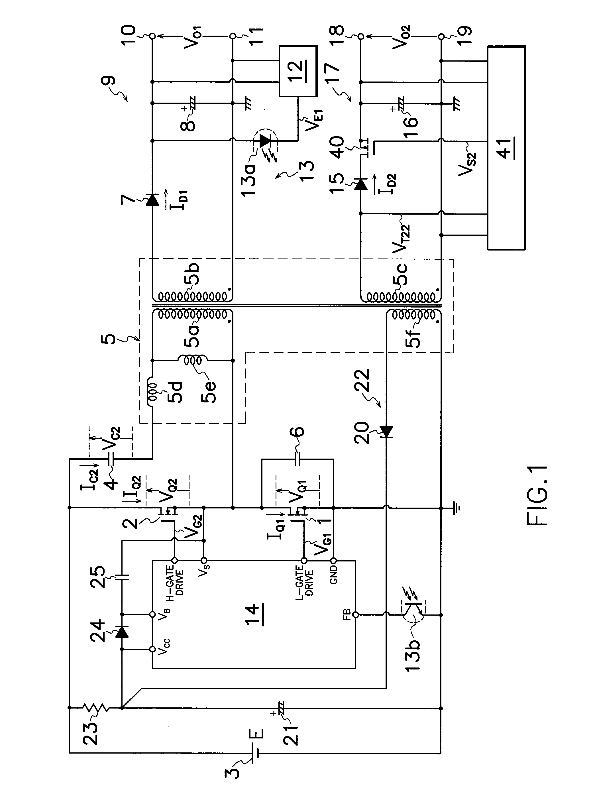
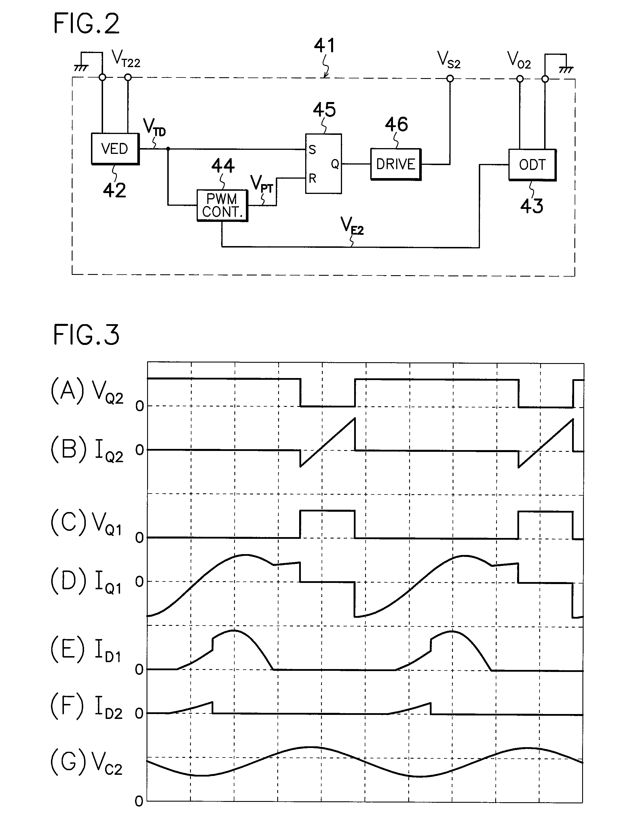
[0064]FIG. 1 illustrates an electric circuit diagram of a first embodiment according to the present invention's current resonant DC-DC converter of multi-output type which comprises an output-regulatory MOS-FET 40 as an output-regulatory switching element connected between a cathode terminal of second output rectifying diode 15 in second rectifying smoother 17 and second output smoothing capacitor 16, and an output control circuit 41 connected to second DC output terminals 18 and 19 and a gate terminal of output-regulatory MOS-FET 40 for controlling the on-off operation of MOS-FET 40 based on voltage VO2 in second output rectifying capacitor 16, while omitting stepdown chopper 30 and chopper controller 31 shown in FIG. 35. In operation, output-regulatory MOS-FET 40 is turned on and off with the same switching frequency of first main MOS-FET 1 and in synchronization with the on-period of first main MOS-FET 1. Simultaneously, main control circuit 14 produces drive signals VG1 and VG2 ...

second embodiment

[0072]The DC-DC converter shown in FIG. 1 can be modified in various ways. For example, the current resonant DC-DC converter of multi-output type according to the present invention comprises a third secondary winding 5g as an additional secondary winding provided in transformer 5 shown in FIG. 4, a third rectifying smoother 49 as an additional rectifying smoother which comprises a third output rectifying diode 47 and a third output smoothing capacitor 48 connected to third secondary winding 5g, an additional output-regulatory MOS-FET 50 as an additional switching element connected between a cathode terminal of third output rectifying diode 47 and third output smoothing capacitor 48, and an additional control circuit 53 for controlling the on-off operation of additional output-regulatory MOS-FET 50 based on the level of voltage VO3 on third output smoothing capacitor 48 connected between third DC output terminals 51 and 52 and additional output-regulatory MOS-FET 50. Third secondary ...

fourth embodiment

[0076]the current resonant DC-DC converter of multi-output type shown in FIG. 6 according to the invention, comprises output-regulatory MOS-FET 40 moved from a positive line shown in FIG. 4 to a ground line between second secondary winding 5c of transformer 5 and second output smoothing capacitor 16, third secondary winding 5g of transformer 5 provided in the adverse polarity to FIG. 4, and third output rectifying diode 47 moved from positive line of FIG. 4 to ground line between third secondary winding 5g of transformer 5 and third output smoothing capacitor 48. Other configurations are similar to those in the DC-DC converter shown in FIG. 4, and operation of the converter shown in FIG. 6 is substantially similar to that in the converter shown in FIG. 1.

[0077]The converter shown in FIG. 6 can attain the almost unchanged period of supplying electric energy from primary to secondary side of transformer 5 although load fluctuates, while obtaining similar functions and effects to those...


PUM


Abstract

A current resonant DC-DC converter of multi-output type is provided which comprises an output-regulatory MOS-FET 40 connected between a secondary winding 5c of a transformer 5 and a smoothing capacitor 16 in a second rectifying smoother 17, and an output control circuit 41 for controlling the on-off operation of output-regulatory MOS-FET 40 based on voltage VO2 from smoothing capacitor 16 in second rectifying smoother 17. By turning the on-off operation of output-regulatory MOS-FET 40 in synchronization with switching frequency of first or second MOS-FETs 1, 2, an ideal cross regulation among respective DC outputs can be obtained, providing the inexpensive converter with simple circuit alteration capable of producing highly stable DC outputs with high power conversion efficiency, high accuracy and less power conversion loss.

Description

TECHNICAL FIELD[0001]This invention relates to a current resonance DC-DC converter of multi-output type for producing a plurality of DC outputs, in particular, of the type of capable of improving entire power conversion efficiency by reducing switching loss of output control switching element in a secondary side of the converter.BACKGROUND OF THE ART[0002]A prior art DC-DC converter of multi-output type comprises a switching element turned on and off to convert DC input from a DC power source into high frequency power which is supplied to a primary winding of a transformer so that the high frequency power is again converted into a plurality of DC powers through rectifying smoothers connected to a plurality of secondary windings in the transformer to produce a plurality of DC powers from each rectifying smoother. Such DC-DC converters have been used in information appliances such as personal computers and domestic appliances such as air conditioners and audio and visual electric prod...

Claims


Application Information

Patent Timeline
Patent Type & Authority Applications(United States)
IPC IPC(8): H02M3/28
CPCH02M3/33561Y02B70/1433H02M3/33576Y02B70/10H02M3/28
Inventor USUI, HIROSHIKAMINAGA, YUKIHIROOSAKA, SYOHEI
Owner SANKEN ELECTRIC CO LTD
Why Eureka
Try Eureka