Electro-optic lenses for correction of higher order aberrations

Active Publication Date: 2009-11-12
E VISION SMART OPTICS INC
View PDF102 Cites 92 Cited by
  • Summary
  • Abstract
  • Description
  • Claims
  • Application Information

AI Technical Summary

Benefits of technology

[0016]In an embodiment of the invention, a lens system may include a lens having an electro-active element, a sensor for sensing pupil size, a controller in operative communication with the sensor, and a plurality of pixelated electrodes electrically connected to the controller. The controller applies a first set of voltages to the plurality of pixelated electrodes corresponding to a first sensed pupil size and a second set of voltages to the plurality of pixelated electrodes corresponding to a second sensed pupil size. The application of voltage causes a change in the refractive index of the lens for correcting a higher order aberration of the eye corresponding to the sensed pupil size.
[0017]In an embodiment of t

Problems solved by technology

Although a lens for correcting a fixed amount of spherical aberration is known, other problems arise.
The amount of spherical aberration that is revealed in the eye typically affects the optical quality of the eye.
It is also known that as the diameter of the pupil changes, other higher o

Method used


Image

  • Electro-optic lenses for correction of higher order aberrations
  • Electro-optic lenses for correction of higher order aberrations
  • Electro-optic lenses for correction of higher order aberrations

Examples


first embodiment

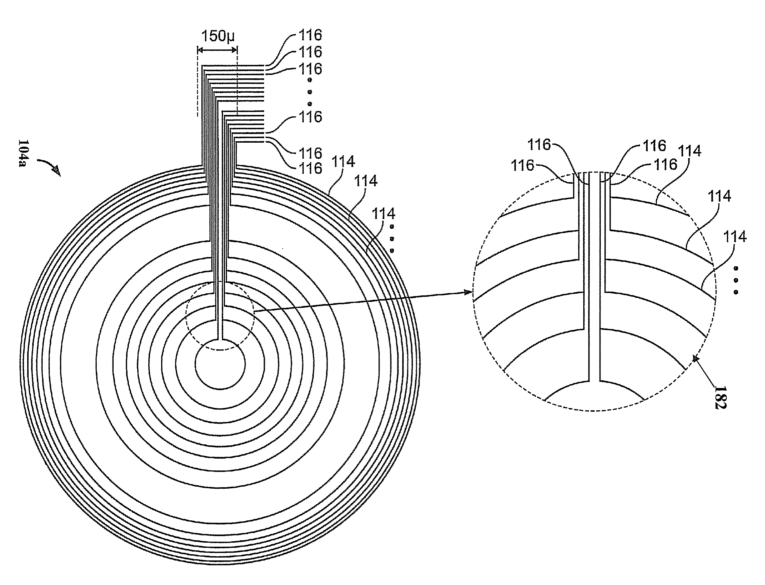
[0046]FIG. 6B shows a front view of a patterned electrode layer for use in the lens of FIG. 6A for correcting spherical aberration of an eye according to the invention. The patterned electrode layer has a plurality of concentric electrode rings 104a. The plurality of electrode rings 104a are, e.g., concentric with the geometric center of the lens. The electrode rings cover a surface of the lens extending radially from the center of the lens to a radius of between approximately 10 mm and approximately 20 mm, although larger radii are possible. The electrode rings are, e.g., circular, although other geometries such as elliptical or polygonal geometries may alternatively be used. Although 16 electrode rings are shown, any number of rings may be used. The number of electrode rings is typically between 2 and 100, and preferably between 10 and 20. The electrode rings are optically transparent. The electrode rings are composed of any of the known transparent conductive metallics, e.g., ind...

second embodiment

[0049]FIG. 6E shows a front view of a patterned electrode layer for use in the lens of FIG. 6A for correcting spherical aberration of an eye according to the invention. The patterned electrode layer has a plurality of concentric electrode rings 104b. The electrode rings 104b of FIG. 6E are significantly narrower than the electrode rings 104a of FIG. 6B (e.g., by a factor of 50). For example, the width of each of the electrode rings 104b of FIG. 6E is less than approximately 100 μm, and preferably approximately 10 μm. Additionally, the spaces between adjacent electrode rings 104b of FIG. 6E are significantly wider (e.g., by a factor or 50). These spaces are occupied by a resistive material. The resistive material is more conductive than the insulating material used between the adjacent electrode rings 104a of FIG. 6B. These and other differences between the patterned electrode layers of FIGS. 6B and 6E are described in further detail below in reference to the cross-sectional views th...

third embodiment

[0074]FIG. 8A shows a front view of a patterned electrode layer for use in the lens of FIG. 6A for correcting all higher order aberration of an eye according to the invention.

[0075]The patterned electrode layer has a plurality of pixelated electrodes 162. Pixelated electrodes may be an array of electrodes localized at different positions on a surface of the lens substrate. In contrast with the electrode rings of FIGS. 6B and 6E, which encircle a lens surface and are concentric with a common point, each of the pixelated electrodes of FIG. 8A has a different center point (e.g., the center of the electrode itself). The pixelated electrodes may be individually addressable electrodes arranged to accommodate a complex voltage pattern to generate an optical phase profile to negate that caused by any or all of the higher order aberrations of the eye. Since the optical phase profile needed for correcting an arbitrary aberrated wavefront is typically asymmetric pixelated electrodes are needed...


PUM


Abstract

A lens is presented in which the lens includes a substrate and an electrode layer. The electrode layer is positioned upon the substrate. The electrode layer has radially alternating rings of electrodes and resistive material. When voltage is applied across two adjacent electrodes the profile of the electric field therebetween is linear. When voltage is applied to the rings of electrodes, the optical phase profile of the lens closely approximates the optical phase of ideal spherical aberration correction.

Description

CROSS REFERENCE TO RELATED APPLICATIONS[0001]This application is a continuation-in-part of U.S. Ser. No. 12 / 135,587 filed on Jun. 9, 2008 and entitled “Adjustable Correction for a Variety of Ambient Lighting Conditions”.[0002]This application claims priority from and incorporates by reference in its entirety U.S. Ser. No. 61 / 039,181 filed on Mar. 25, 2008 and entitled “Electro-Optic Lenses for Correction of Higher Order Aberrations.”GOVERNMENT INTEREST STATEMENT[0003]This invention was made in whole or in part with government support under Contract Number FA7014-07-C-0013, awarded by the U.S. Air Force, Office of the Surgeon General (AF / SG). The government may have certain rights in the invention.BACKGROUND OF THE INVENTION[0004]A perfect lens focuses light to a single point on an optical axis of the lens. An aberration of the lens of an eye is a deviation from the perfect focusing of light due to a distortion of a wavefront of light as it passes through the eye having irregularitie...

Claims


Application Information

Patent Timeline
IPC IPC(8): G02C7/06G02F1/29A61B3/11
CPCG02C7/061G02C2202/22G02C7/101G02C7/083G02F1/134309G02F1/294
Inventor MCGINN, JOSEPH THOMASDUSTON, DWIGHT P.VAN HEUGTEN, ANTHONY
Owner E VISION SMART OPTICS INC
Why Eureka
Try Eureka