Method and System for Identifying Defects in NDT Image Data

Active Publication Date: 2009-11-12
GENERAL ELECTRIC CO
View PDF18 Cites 108 Cited by
  • Summary
  • Abstract
  • Description
  • Claims
  • Application Information

AI Technical Summary

Benefits of technology

[0015]FIG. 7 is a graph illustrating cumulative density function (CDF)

Problems solved by technology

However, and as will be appreciated by those skilled in the art, owing to the structural complexity and large production volumes of these castings, the manual inspection procedure is often prone to operator fatigue and hence suffers from low insp

Method used


Image

  • Method and System for Identifying Defects in NDT Image Data
  • Method and System for Identifying Defects in NDT Image Data
  • Method and System for Identifying Defects in NDT Image Data

Examples


Embodiment Construction

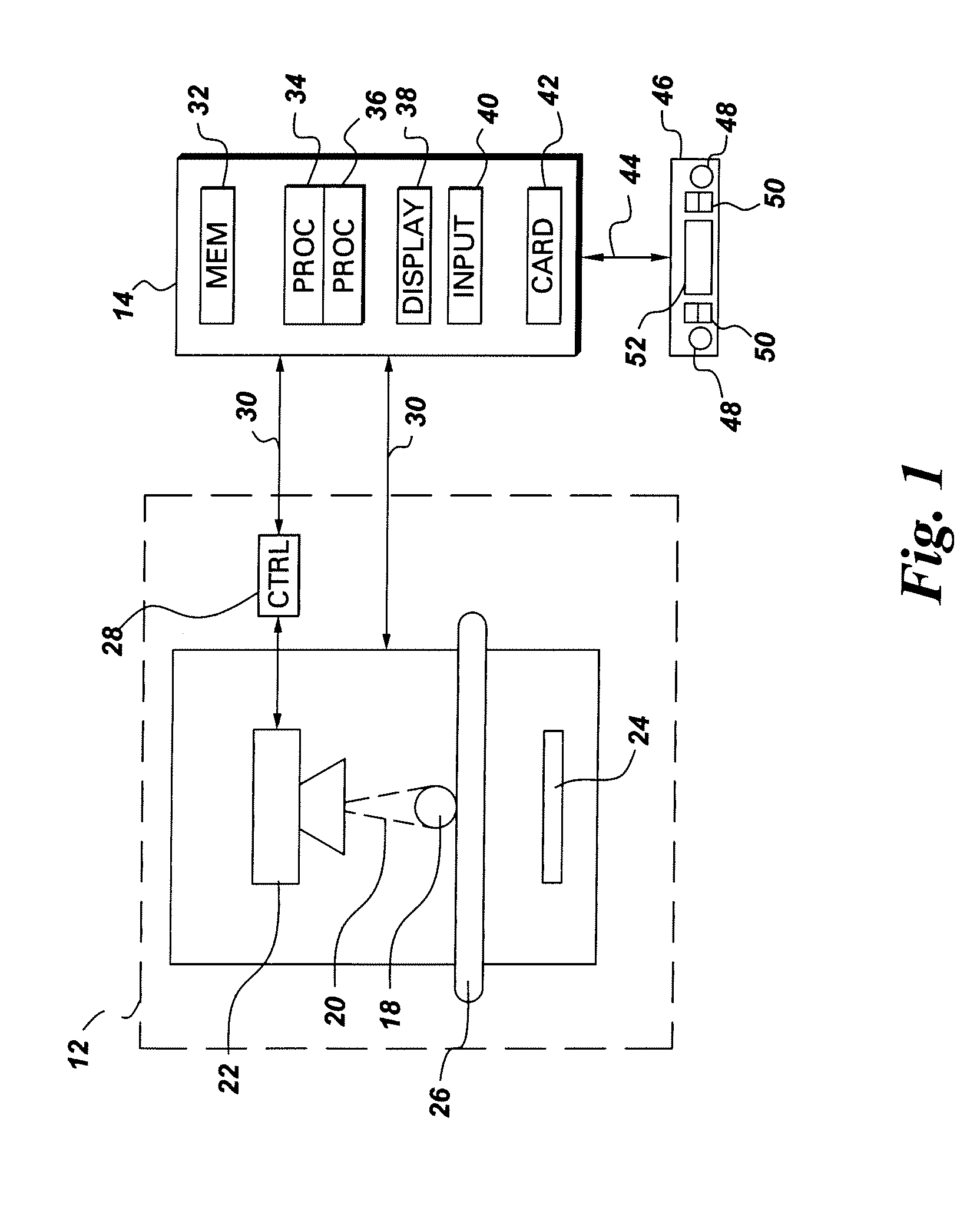
[0016]FIG. 1 is an illustration of an exemplary radiographic inspection system for processing a radiographic image of a scanned object. It should be noted that although the illustrated example is directed to radiography, the present invention is equally applicable to other inspection modalities, non-limiting examples of which include X-ray, CT, infrared, eddy current, ultrasound and optical. Referring to FIG. 1, the radiographic inspection system 10 includes a computer system 14 adapted to be in signal communication with an imaging system 12 via a communication bus 30. A real-time image controller 46 is adapted to be in signal communication with the computer system 14 via another communication bus 44. The imaging system 12 is configured to acquire and output radiographic image data corresponding to a scanned object 18 via an imaging device 16. The imaging system may include, but is not limited to, an X-ray system, a CT system, an infra-red system, an eddy current system, an ultrasou...


PUM


Abstract

An anomaly detection method includes acquiring image data corresponding to nondestructive testing (NDT) of a scanned object. The NDT image data comprises at least one inspection test image of the scanned object and multiple reference images for the scanned object. The anomaly detection method further includes generating an anomaly detection model based on a statistical analysis of one or more image features in the reference images for the scanned object and identifying one or more defects in the inspection test image, based on the anomaly detection model.

Description

BACKGROUND[0001]The invention relates generally to nondestructive testing (NDT) of parts and more particularly to a method and system for automatically identifying defects in NDT image data corresponding to a scanned object.[0002]NDT is a technique of producing relevant data for an object by collecting energy emitted by or transmitted through the object, such as by penetrating radiation (gamma rays, X-rays, neutrons, charged particles, etc.) sound waves, or light (infrared, ultraviolet, visible, etc.). The manner by which energy is transmitted through or emitted by any object depends upon variations in object thickness, density, and chemical composition. The energy emergent from the object is collected by appropriate detectors to form an image or object map, which may then be realized on an image detection medium, such as a radiation sensitive detector. A radiographic detector, for example, comprises an array of elements that records the incident energy at each element position, and...

Claims


Application Information

Patent Timeline
IPC IPC(8): G06K9/00
CPCG06K9/6298G06T7/001G06T7/0034G06T2207/30108G06T2207/20076G06T2207/20081G06T2207/10116G06T7/35G06F18/10
Inventor SUN, ZHAOHUICAN, ALIJANNING, JOHN CHARLESKAUCIC, ROBERT AUGUSTMENDONCA, PAULO RICARDOPORTAZ, JOSEPH MANUEL
Owner GENERAL ELECTRIC CO
Why Eureka
Try Eureka