Image processing device and method

a technology of image processing and video image, which is applied in the field of image processing device and method, can solve the problems of inability to create 3d video in real-time from video images captured by a single camera, high-definition video camera arrays for capturing 3d images are very expensive, and users' eyes are uncomfortable and headaches

Inactive Publication Date: 2010-08-19
SONY CORP
View PDF6 Cites 119 Cited by
  • Summary
  • Abstract
  • Description
  • Claims
  • Application Information

AI Technical Summary

Benefits of technology

[0013]Embodiments of the present invention advantageously allow video coverage of, for example, sports events to be captured by a high definition camera and then processed so as to form 3D images. Accordingly, embodiments of the invention can derive an offset amount for each detected object within a scene based on a detected distance between a reference position (such as the position of the camera) and the object. When the captured image (e.g. left-hand image) and the modified image (e.g. right-hand image) are viewed together as a pair of images on a display, the object will appear to be positioned at a predetermined distance from the display. This advantageously allows 3D images to be generated without the need for expensive stereo pairs of cameras or time consuming post-processing operations.

Problems solved by technology

However, current high definition video camera arrays for capturing 3D images are very expensive.
Furthermore, mismatches in image luminance and chrominance between the two cameras can cause eye discomfort and headaches for a user as the brain will try and make the two images appear to be the same.
As well as being expensive, this process can be very time consuming and labour intensive, thus meaning that it is likely to be impossible to create 3D video in real-time from video images captured by a single camera.

Method used


Image

  • Image processing device and method
  • Image processing device and method
  • Image processing device and method

Examples


Embodiment Construction

[0029]An image processing device and image processing method are disclosed. In the following description, a number of specific details are presented in order to provide a thorough understanding of embodiments of the present invention. It will be apparent however to a person skilled in the art that these specific details need not be employed to practice the present invention. Conversely, specific details known to the person skilled in the art are omitted for the purposes of clarity in presenting the embodiments.

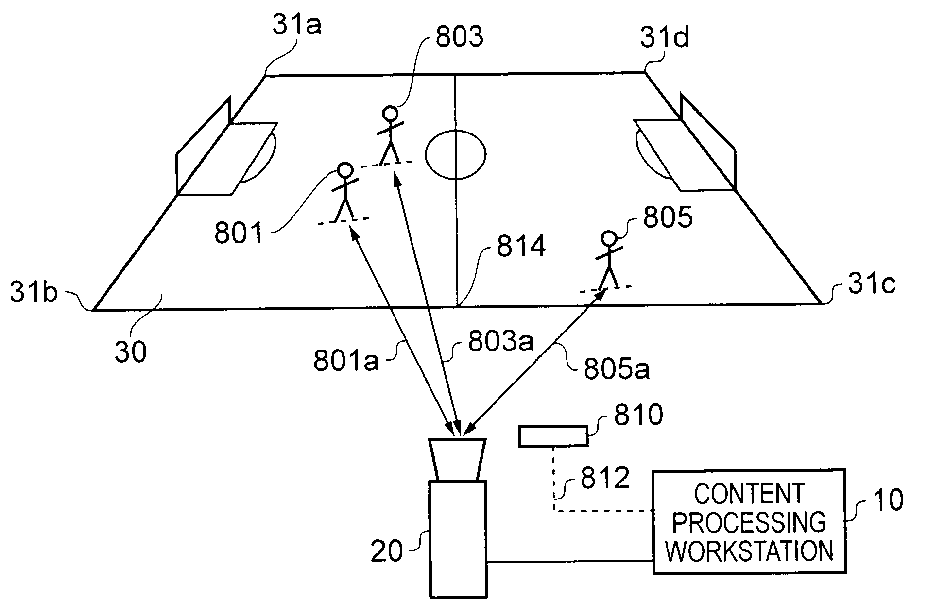
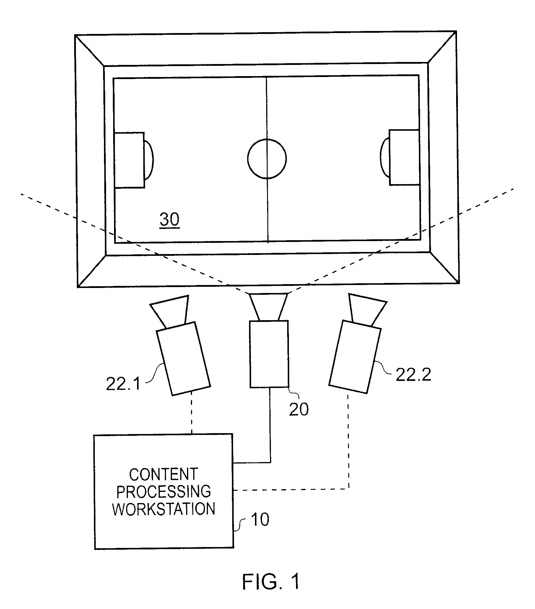
[0030]FIG. 1 shows a schematic diagram of an object tracking system in accordance with examples of the present invention. In the example shown in FIG. 1, the objects to be tracked are football players (not shown) on a football pitch 30. High definition (HD) video images (1920 by 1080 pixels) of the pitch 30 are captured by one or more high definition cameras. Although, examples of the present invention can be used to track objects in video images from more than one camera, in ...


PUM


Abstract

An image processing device comprises receiving means operable to receive, from a camera, a captured image corresponding to an image of a scene captured by the camera. The scene contains at least one object. The device comprises determining means operable to determine a distance between the object within the scene and a reference position defined with respect to the camera, and generating means operable to detect a position of the object within the captured image, and to generate a modified image from the captured image based on image features within the captured image which correspond to the object in the scene. The generating means is operable to generate the modified image by displacing the position of the captured object within the modified image with respect to the determined position of the object within the captured image by an object offset amount which is dependent on the distance between the reference position and the object in the scene so that, when the modified image and the captured image are viewed together as a pair of images on a display, the captured object appears to be positioned at a predetermined distance from the display.

Description

BACKGROUND OF THE INVENTION[0001]1. Field of the Invention[0002]The present invention relates to an image processing device and method.[0003]2. Description of the Prior Art[0004]Stereoscopic imaging in which a stereo pair of images may be viewed together so as to give an appearance of a three dimensional image has been popular for over a century. To create an illusion that an image is three-dimensional (3D), two slightly different images may be viewed together so that one of the images is viewed by a user's left eye and the other image is viewed by a user's right eye. Provided that the two images correspond to two slightly different views of the same scene (for example each image in the pair being as if seen from the user's left eye and right eye respectively), the user's brain will fool the user into thinking that the pair of images is one three dimensional image when the images are viewed in a suitable manner. An object within the images will appear at an apparent depth from the d...

Claims


Application Information

Patent Timeline
Patent Type & Authority Applications(United States)
IPC IPC(8): G06K9/00H04N13/122
CPCH04N13/0207H04N13/0018H04N13/207H04N13/122G06T15/205H04N13/00
Inventor PORTER, ROBERT MARK STEFANGILLARD, CLIVE HENRY
Owner SONY CORP
Why Eureka
Try Eureka