
Radio communication apparatus and radio communication method

a radio communication and radio communication technology, applied in the field of radio communication apparatus and radio communication methods, can solve the problems of higher computational complexity and convergence, and achieve the effect of reducing computational complexity

Inactive Publication Date: 2009-11-12
NTT DOCOMO INC
View PDF8 Cites 13 Cited by
  • Summary
  • Abstract
  • Description
  • Claims
  • Application Information

AI Technical Summary

Benefits of technology

[0012]Accordingly, it is an object of the present invention to provide radio communication apparatus and method that can calculate an optimum transmit power allocation to individual users while reducing the computational complexity associated with that calculation under the situation where respective transmit power levels are constrained for different transmit antennas and different groups of transmit antennas.
[0015]According to the aspects of the present invention, optimum transmit power levels can be allocated for individual users while reducing the computational complexity associated with that calculation under the situation where respective transmit power levels are constrained for different transmit antennas and different groups of transmit antennas.

Problems solved by technology

The power allocation optimization problems as stated above correspond to constrained nonlinear optimization problems, and higher computational complexity may be required to solve them.
For example, in the case where the power allocation optimization problems are solved with use of an interior point method in accordance with a steepest descent method, the solution can be analytically obtained in a relatively simple algorithm, but higher computational complexity may be required for convergence.

Method used


Image

  • Radio communication apparatus and radio communication method
  • Radio communication apparatus and radio communication method
  • Radio communication apparatus and radio communication method

Examples


first embodiment

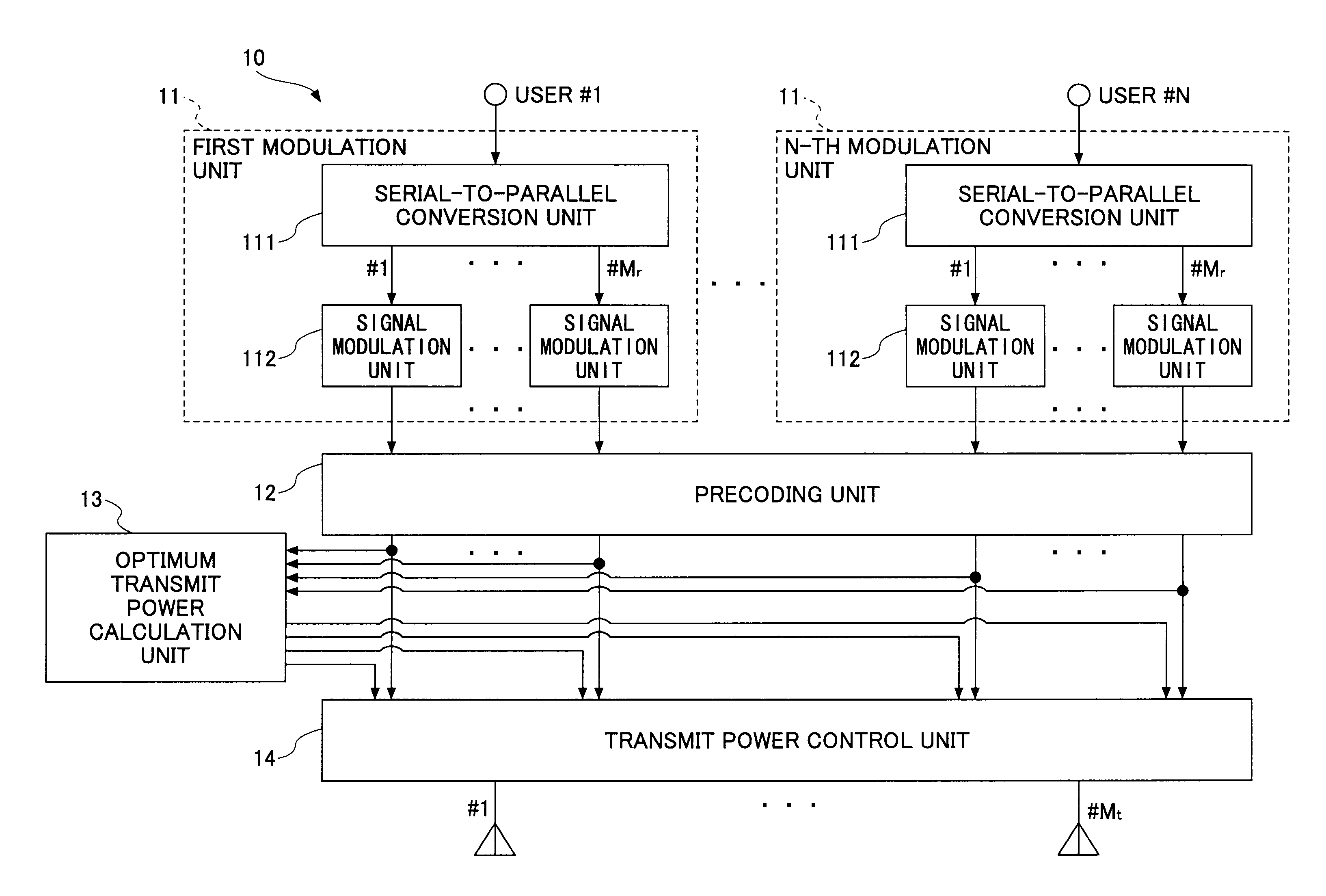
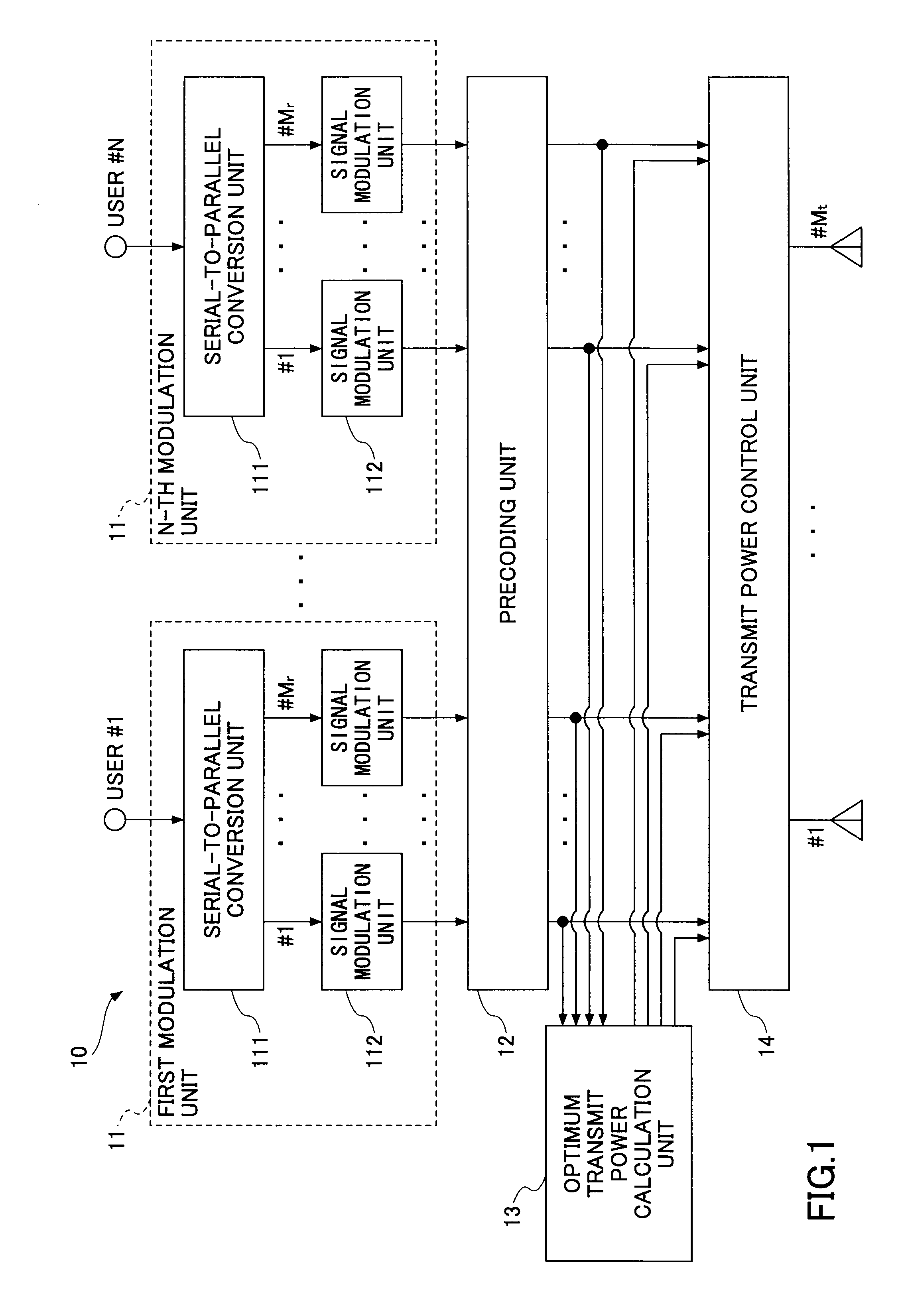
[0042]FIG. 1 illustrates an exemplary arrangement of a radio communication apparatus 10 according to the first embodiment. As illustrated in FIG. 1, the radio communication apparatus 10 includes a number of modulation units 11 corresponding to the number (N) of users, a preceding unit 12, an optimum transmit power calculation unit 13 and a transmit power control unit 14. Each of the modulation units 11 includes a serial-to-parallel conversion unit 111 and signal modulation units 112.

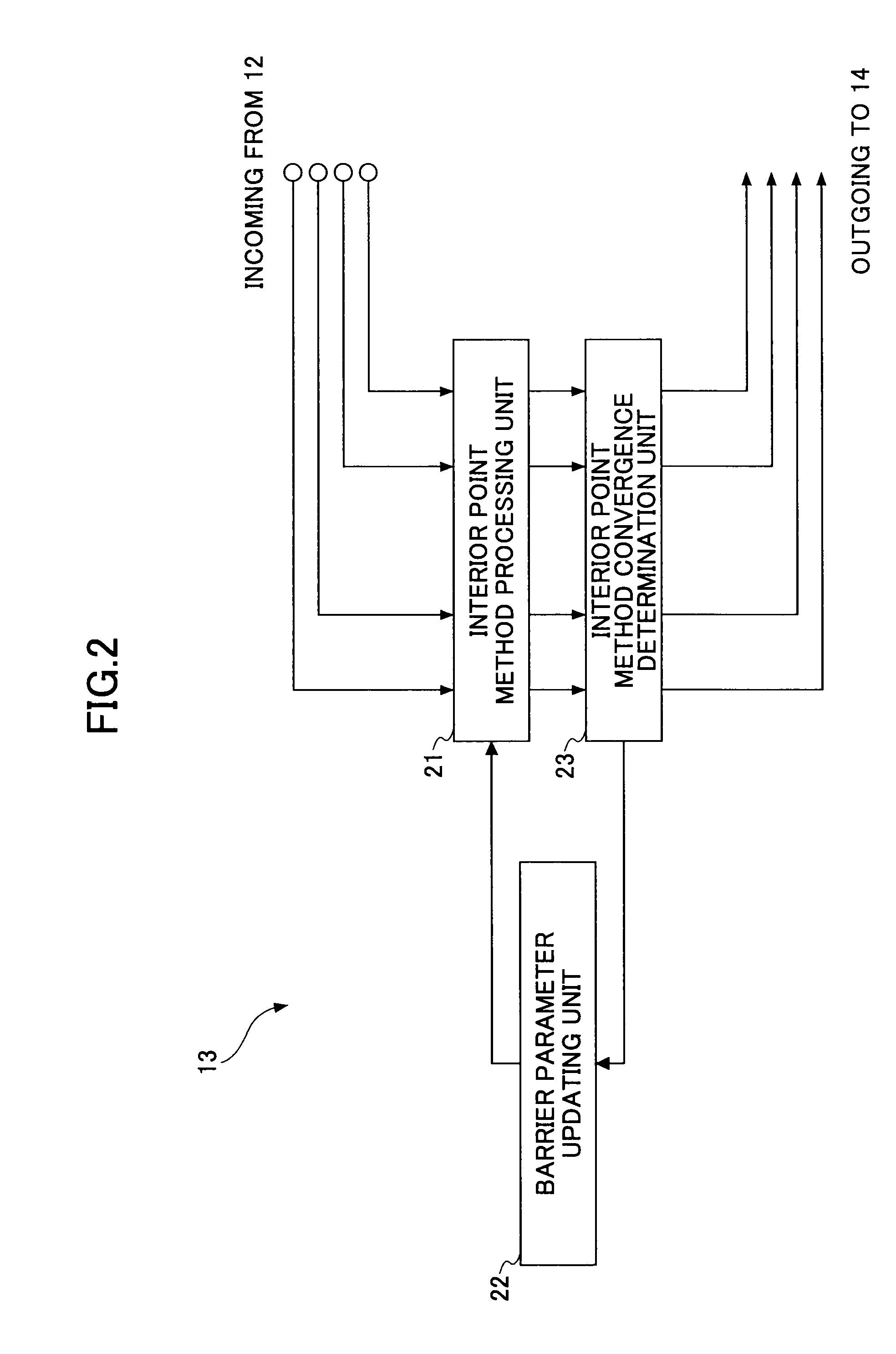
[0043]FIG. 2 illustrates an exemplary arrangement of the optimum transmit power calculation unit 13 according to the first embodiment. The optimum transmit power calculation unit 13 includes an interior point method processing unit 21, a barrier parameter updating unit 22 and an interior point method convergence determination unit 23.

[0044]FIG. 3 illustrates an exemplary arrangement of the barrier parameter updating unit 22 according to the first embodiment. The barrier parameter updating unit 22 include...

second embodiment

[0095]In the first embodiment, it is assumed that multiple transmit antennas are installed on a radio communication apparatus. In the second embodiment, multiple transmit antennas may be separated from a radio communication apparatus and be coupled to the radio communication apparatus in a wired and / or wireless manner.

[0096]FIG. 11 illustrates a radio communication apparatus according to the second embodiment of the present invention. A radio communication apparatus is coupled to transmit antenna units 1As each having multiple transmit antennas in a wired and / or wireless manner.

[0097]In operation, the radio communication apparatus 10 may operate in a similar manner to that of the first embodiment except that the radio communication apparatus 10 is separated from the transmit antenna units 1As.

[Application Instance]

[0098]An exemplary application instance for the first embodiment as mentioned above is described below. In order to validate the effectiveness of the present embodiment, s...


PUM


Abstract

A disclosed radio communication apparatus includes a preceding unit, a optimum transmit power calculation unit and a transmission unit. The optimum transmit power calculation unit receives the transmit weight related information from the preceding unit and calculates a transmit power level to optimize an objective function in accordance with an interior point method. The objective function results from addition of a barrier function adjusted with a barrier parameter to an original objective function associated with a constrained optimization problem. The original objective function includes a function of respective channel capacities for individual users derived from the transmit weight related information. The optimum transmit power calculation unit adaptively updates a logarithm of the barrier parameter and uses a gradient obtained through a high-order derivative with the logarithm of the barrier parameter to calculate the transmit power level to optimize the resulting objective function.

Description

BACKGROUND OF THE INVENTION[0001]1. Field of the Invention[0002]Embodiments discussed herein are directed to an apparatus and method for radio communication under the condition where some constraints on transmit power levels are applied for each transmit antenna or each group of transmit antennas in multi-user MIMO downlinks.[0003]2. Description of the Related Art[0004]In recent years, a MIMO (Multiple-Input Multiple-Output) transmission scheme has been intensively investigated for improvement of frequency or spectral efficiency and increase in communication capacity. In this MIMO transmission scheme, a multi-user (MU)-MIMO system designed to apply the MIMO transmission scheme to multiple users for further improvement of the spectral efficiency is attracting attention. Furthermore, a system designed for MU-MIMO coordinated base stations transmission is being studied, and it is reported that it can realize significant improvement of throughput.[0005]In this MU-MIMO coordinated base s...

Claims


Application Information

Patent Timeline
IPC IPC(8): H04B7/00
CPCH04B7/0417H04B7/0617H04W52/346H04W52/343H04B7/0619
Inventor OHWATARI, YUSUKEBENJEBBOUR, ANASSOOYA, TOMOYUKIHAGIWARA, JUNICHIRO
Owner NTT DOCOMO INC
Learn More