Mobile holographic simulator of bowling pins and virtual objects
a virtual object and bowling pin technology, applied in the field of virtual object holographic simulator of bowling pins, can solve the problems of slowness, cumbersome, cumbersome, cumbersome, etc., and achieve the best possible realistic
Inactive Publication Date: 2009-11-12
ZAMBELLI SILVIA
View PDF4 Cites 31 Cited by
- Summary
- Abstract
- Description
- Claims
- Application Information
AI Technical Summary
Benefits of technology
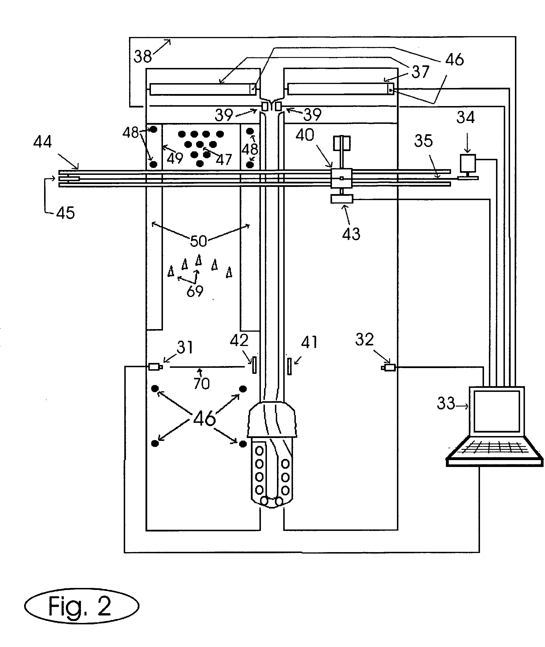
[0009]When reading the first and the last lane, the sensor receives a double input, considering that the reflex reflector (61) consists of two reflex reflectors separated by a small non-reflecting gap. In this way, the control unit (15) (33) realises whether it is at the end or the beginning of the tracks. At this stage, the control unit (15)(33) sends an electrical signal to the control unit of the holographic pinsetter (8)(43) to instruct it to start the simulation. The above-mentioned transport system may not be installed and, if this is the case, each lane has a holographic pinsetter and the functions performed by the control unit (15) (33) and described in this report, are carried out by control units (8) and (43). This solution offers a few advantages: it is quicker, since there is no need to transport it to the lane required, in which case the costs are naturally higher.
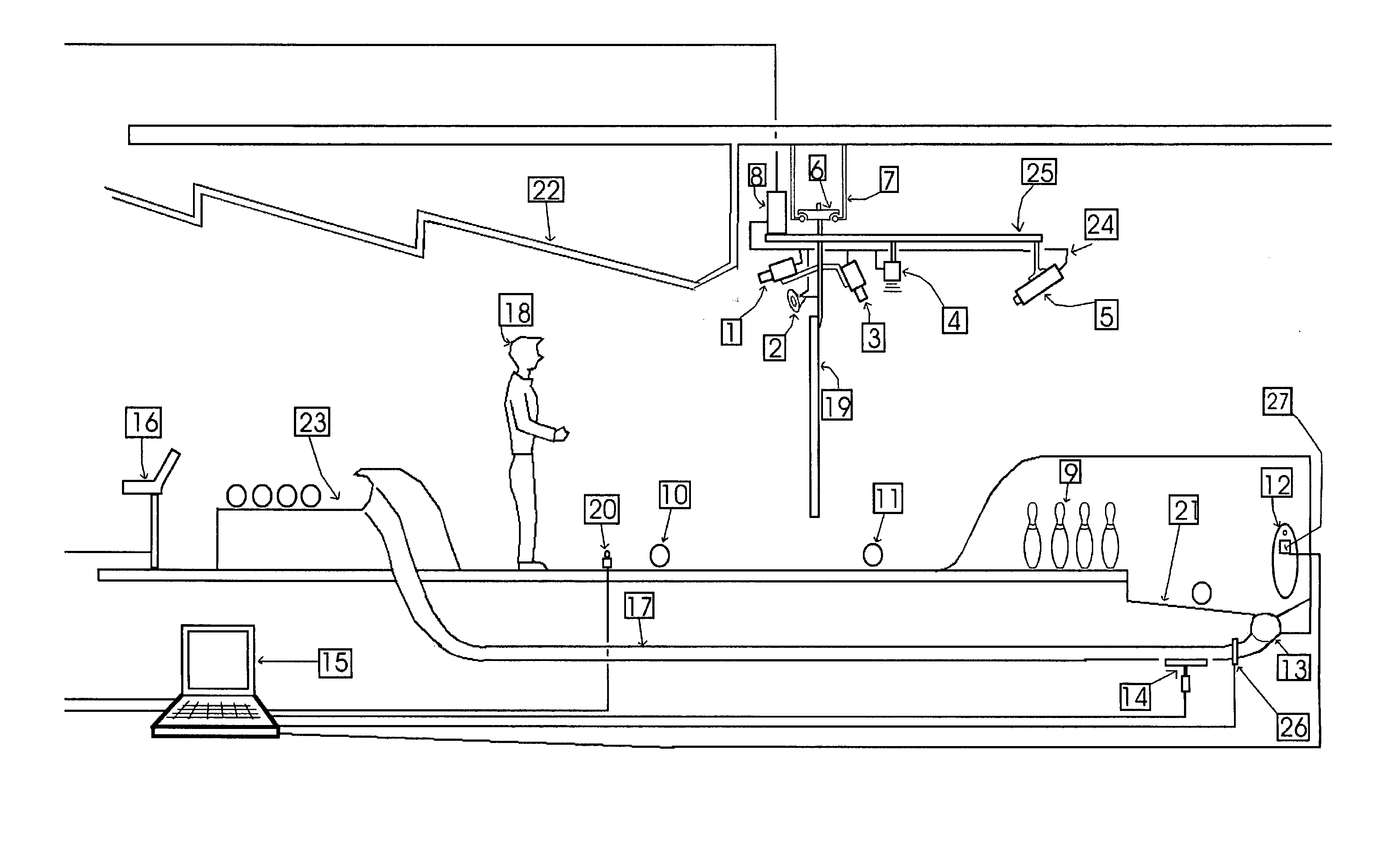
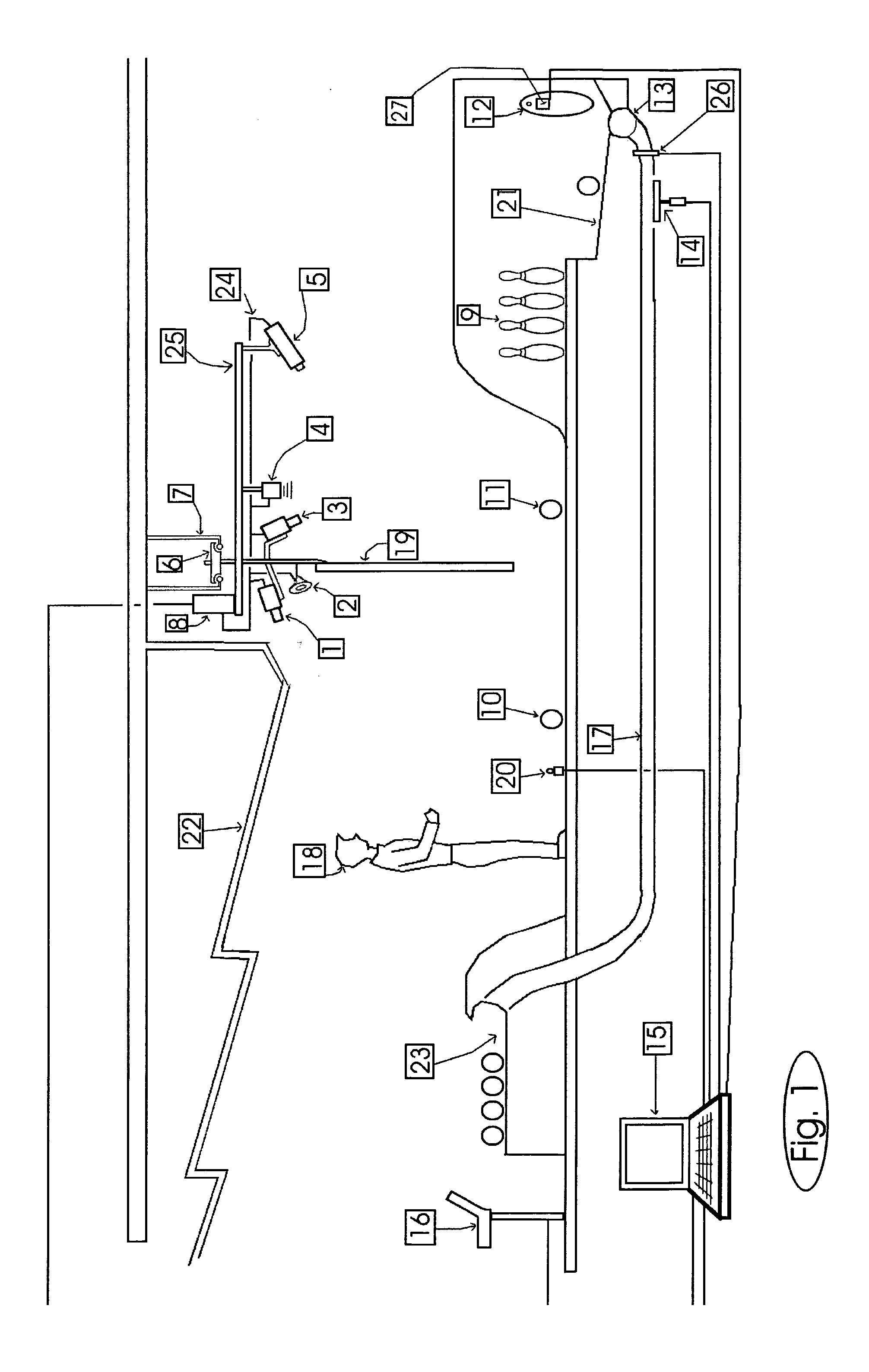
[0040]Ball (f.3) (10) (11): The ball contains a control unit (52), which transmits an unmistakable code in radio frequency (57) (58) that depends on the weight and dimensions of the ball. The control unit (52) sends a code to the rf-reader (4) as the ball (11) passes under the screen (19), then the control unit (8) converts the code into the real weight and dimensions of the ball. In this way, each time the ball rolls past, the control unit is capable of knowing with which weight and diameter the physical simulation of the game is to be constructed. The ball contains a gyroscopic sensor (53), which transmits the angular speed of the ball to the control unit (52) each time the ball passes under the screen; the control unit (52) then transmits this speed to the control unit (8) via a radio frequency transmitter (57) (58). The control unit also triggers a lamp that is built-in the ball (55) (56) only when the ball is moving or better still only when the gyroscopic sensor (53) transmits a movement signal to the control unit (52). The lamp is battery powered (51), which is again fitted inside the ball. This lamp is positioned so that it illuminates the outer surface of the ball from the inside, thus illuminating the actual ball as it rolls along the lane. The battery is re-charged using two contacts (59) arranged in the bottom of the finger holes, which all bowling balls have.
Problems solved by technology
This means that the holographic pinsetter does not need all the mechanical parts, which make mechanical pinsetters the systems most susceptible to wear, slower, expensive, unstable, cumbersome, heavy and generally less efficient.
Method used
View moreImage
Smart ImageViewing Examples
Examples
Embodiment Construction
[0044]As described below.
Login to View More PUM
 Abstract
A system with automatic positioning controls for the holographic display of three-dimensional objects interacting in real time with objects of the real world. The person observing the screen (18) has the sensation that the objects are real, which is achieved thanks to a real time perspective correction system (1). The system is used in particular to simulate bowling pins (9). It is positioned on the lane required by means of a dolly (6). The system determines a relation between the information received from the sensors: video cameras (1) (3), dimensions (26), weight (14) (27) and the mathematical simulation models. When the ball is bowled, its physical features are measured and when it hits the pin deck, some holographic pins are displayed on the screen (19). The screen holographically arranges the projected objects over what the bowler (18) sees behind the screen (19). The simulated movements of the pins and the physical interactions with the real objects are determined by exploiting the theory of mechanics in three-dimensional space.
Description
BACKGROUND ARTDefinitions and Basic Concepts[0001]Tenpin bowling is played on a wooden lane or one of synthetic material, according to the specifications of the American Bowling Club ABC / WIBC. 10 pins are positioned at one end of the lane while the player throws a ball from the other end in the attempt to knockdown as many pins as possible. Please refer to the ABC / WIBC specifications for the complete set of game rules, as this is merely a generic description. There are many types of games, which differ in the number of pins, shape, positions, score rules, shape and dimensions of the lanes, balls and pins; here are the most popular: 10 pin, 9 pin, candle pin, 5 pin, figure, duck pin, red pin. The wooden lane is rectangular, 19 meters long and 3 meters wide and the pins are positioned on top of it. The game is played on the lane, which consists in throwing bowling balls towards the pins in the attempt to knockdown as many pins possible. The pin deck is the minimum square area on which...
Claims
Login to View More Application Information
Patent Timeline
 Patent Type & Authority Applications(United States)
IPC IPC(8): A63D5/00
CPCA63D1/00A63D5/04A63D3/00
Inventor ZAMBELLI, SILVIA
Owner ZAMBELLI SILVIA
Features
- R&D
- Intellectual Property
- Life Sciences
- Materials
- Tech Scout
- Unparalleled Data Quality
- Higher Quality Content
- 60% Fewer Hallucinations
Learn More Browse by: Latest US Patents, China's latest patents, Technical Efficacy Thesaurus, Application Domain, Technology Topic, Popular Technical Reports.
© 2025 PatSnap. All rights reserved.Legal|Privacy policy|Modern Slavery Act Transparency Statement|Sitemap|About US| Contact US: help@patsnap.com


