Medical Device For Diagnosing and Treating Anomalous Tissue and Method for Doing the Same

a medical device and anomalous tissue technology, applied in the field of medical devices for diagnosing and treating anomalous tissue and methods for doing the same, can solve the problems of cosmetic damage, unnecessary tissue removal, affecting the accuracy of analysis,

Inactive Publication Date: 2009-11-12
BECKMAN HUGH +2
View PDF41 Cites 68 Cited by
  • Summary
  • Abstract
  • Description
  • Claims
  • Application Information

AI Technical Summary

Benefits of technology

[0005]In another embodiment, the medical device comprises a probe, a spectrometer coupled to the probe, a database of tissue fingerprints, a controller coupled to the probe and the spectrometer and a first energy source coupled to the probe and configured to emit one or more of a diagnostic excitation, a therapeutic ablation and a diagnostic ablation as directed by the controller or a user on a target tissue. The first energy source delivers excitation energy through the probe to the tissue during the

Problems solved by technology

There are many disadvantages to this treatment system.
There may be unnecessary tissue removal and cosmetic damage.
Lengthy treatment sessions are necessary due to the ma

Method used


Image

  • Medical Device For Diagnosing and Treating Anomalous Tissue and Method for Doing the Same
  • Medical Device For Diagnosing and Treating Anomalous Tissue and Method for Doing the Same
  • Medical Device For Diagnosing and Treating Anomalous Tissue and Method for Doing the Same

Examples


third embodiment

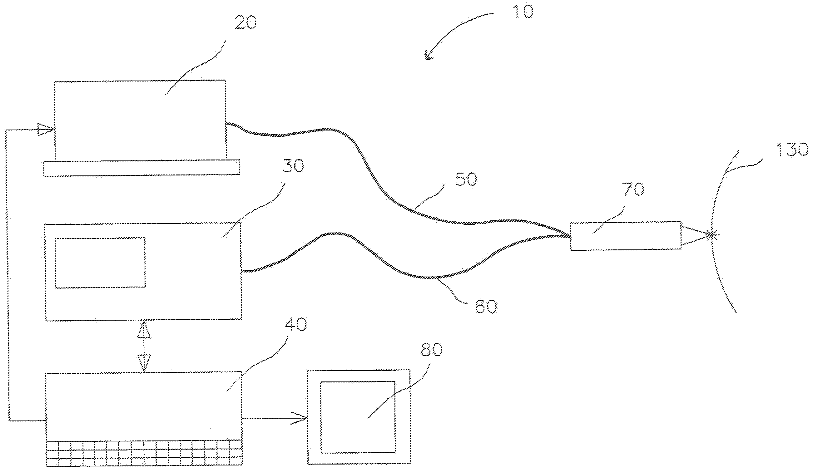
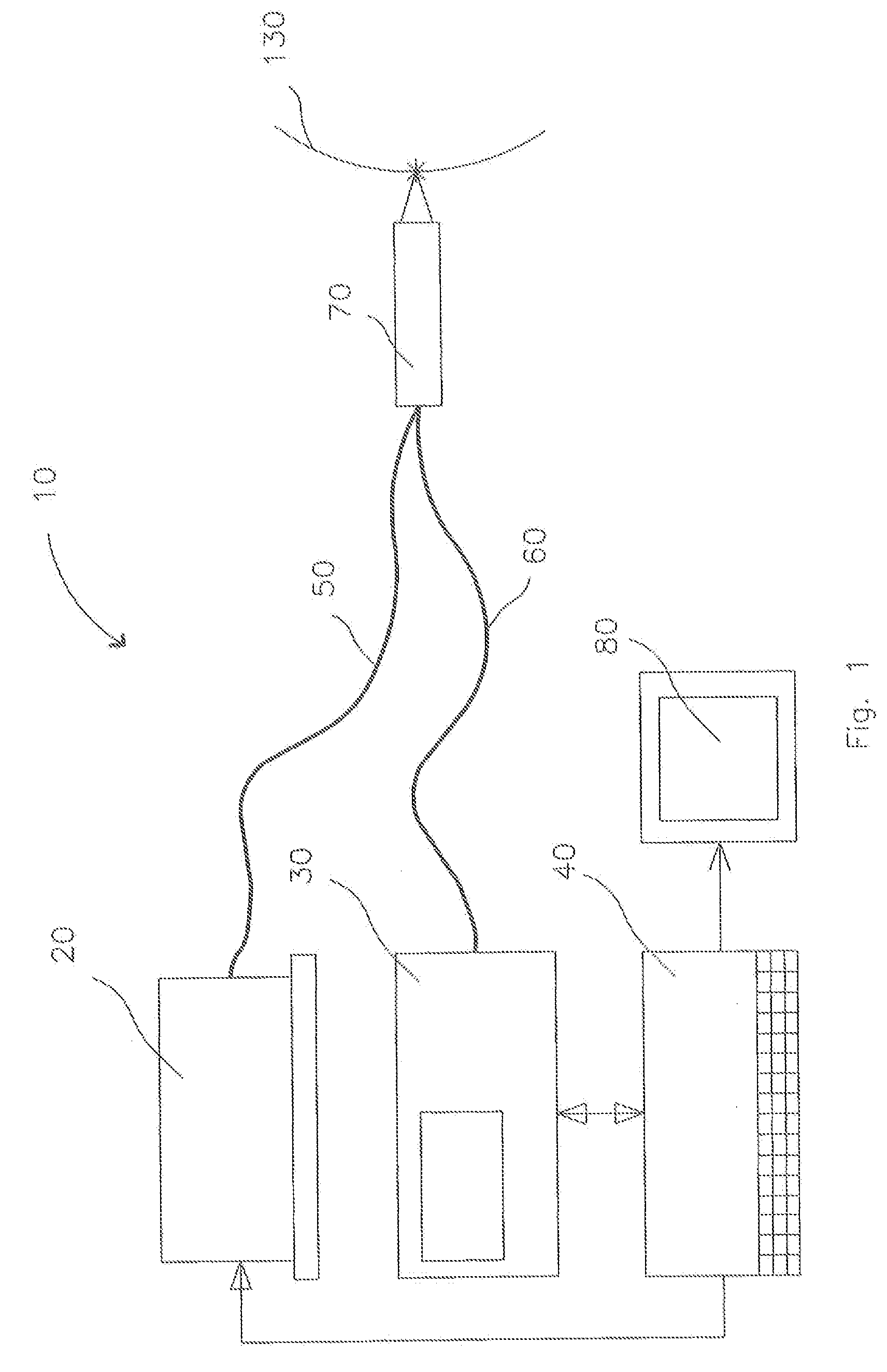
[0038]a probe for use with medical device 10 is shown in FIG. 7. In this embodiment, no focusing optics in or out of the distal end of the probe 270 are used. Protective window 200, described above, is shown as easily replaceable, optionally disposable, and is incorporated into this embodiment.

fourth embodiment

[0039]a probe for use with medical device 10 is shown in FIG. 8. Probe 370 comprises a single conduit 380 that can deliver excitation / ablation energy to target tissue 130 and a lens 390 to focus the energy. In addition, the same conduit 380 can collect the scatter through the same probe 370 and deliver the scatter to the sensor (not shown). Probe 370 can also comprise inert gas catheter 400 that can deliver positive pressure air, nitrogen or other inert gas through hole 410 in the distal end of probe 370. The positive pressure gas blowing through inert gas catheter 400 can protect the contents of probe 370 from debris. As used herein, “debris” is anything resulting from the ablation of the tissue, such as a plume of smoke, blood, ablated tissue remains, and other bodily fluid.

fifth embodiment

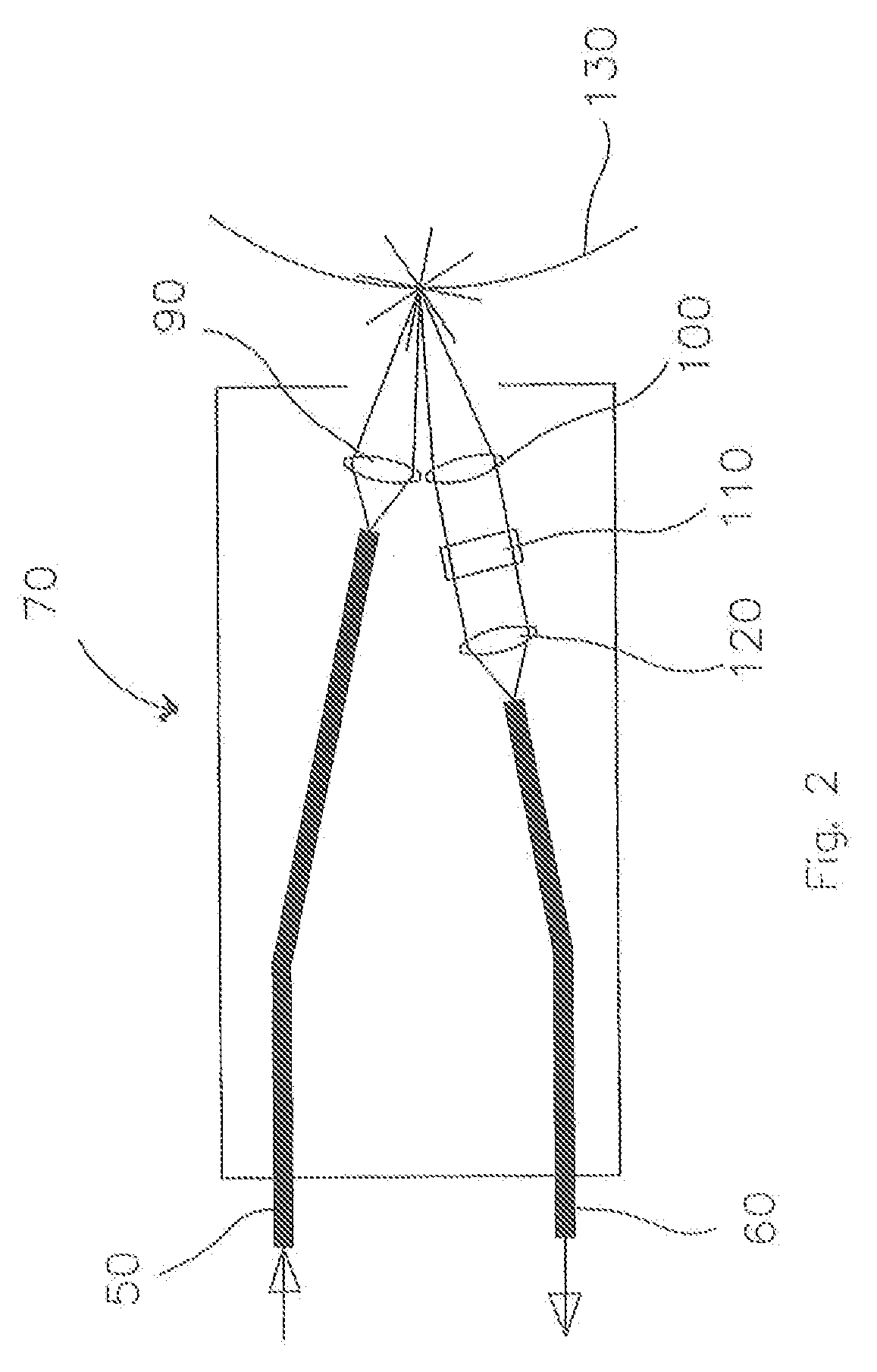
[0040]a probe for use with medical device 10 is shown in FIGS. 9A and 9B. Probe 470 comprises hollow articulating arm 480 such as that used to carry near infrared, carbon dioxide laser emissions from energy source 20 (not shown). FIG. 9A illustrates the entire distal end of articulating arm 480. Adjacent to articulating arm 480 run excitation conduit 490 and sensing conduit 60. A diagnostic excitation beam is delivered to target tissue 130 through excitation conduit 490 from energy source 20 (not shown) or a separate energy source as desired or required. Sensing conduit 60 performs as described above. FIG. 9B is an exploded view of the very distal end of probe 470, showing aiming device 500 used to aid in directing the ablation energy from the carbon dioxide laser to target tissue 130.

[0041]It is contemplated that other useful devices may be incorporated into the probe embodiments as desired or required. For example, a vacuum removal tube can be configured to remove debris from the ...


PUM


Abstract

Disclosed herein are medical devices for diagnosing and treating anomalous tissue and methods of use. One embodiment of the medical device can comprise an energy source configured to emit at least an excitation beam and a therapeutic beam, a probe coupled to the energy source and configured to propagate the excitation and therapeutic beams with the beams capable of contact with the tissue, a sensor coupled to the probe that detects at least one predefined attribute of radiation emanating from the tissue when the tissue is subjected to the excitation beam and a controller coupled to the energy source and the sensor and programmed to selectively alternatively actuate the energy source to emit the excitation beam and the therapeutic beam in response to the detection of the at least one predefined attribute by the sensor.

Description

CROSS-REFERENCE TO RELATED APPLICATION[0001]This application claims priority from U.S. Provisional Application Ser. No. 61 / 051,705, filed May 9, 2008, which is incorporated herein in its entirety by reference.FIELD OF THE INVENTION[0002]The present invention relates in general to devices for diagnosing tissue via detecting spectra and the linking of those devices to a therapeutic modality for the concurrent diagnosis and treatment of abnormal tissue.BACKGROUND[0003]Surgical excision of neoplastic tumor tissue has historically been performed manually using steel blades and lasers. In recent years, robotic devices have been employed to assist the surgeon. Currently, many surgeons advocate the use of the Mohs technique to diagnose and remove malignant tissues. The Mohs technique includes taking a mapped specimen of tumor tissue, staining the tissue, and evaluating the tissue under a microscope to determine the amount and location of the residual tumor cells. In particular, the area wit...

Claims


Application Information

Patent Timeline
IPC IPC(8): A61B18/18A61B6/00A61B18/16A61N7/00
CPCA61B5/0059A61B5/444A61B18/20A61N2005/0659A61N2005/0644A61N2005/0652A61N5/0616
Inventor BECKMAN, HUGHFULLER, TERRY A.BECKMAN, RICHARD L.
Owner BECKMAN HUGH
Why Eureka
Try Eureka