Method and System For Data Disaggregation

a data disaggregation and data technology, applied in the field of data migration, can solve the problems of requiring more power than the server itself, and requiring substantial amounts of power to operate and cool

Inactive Publication Date: 2009-11-12
IBM CORP
View PDF22 Cites 35 Cited by
  • Summary
  • Abstract
  • Description
  • Claims
  • Application Information

AI Technical Summary

Benefits of technology

[0009]These and other objects and advantages are accomplished by a method for migrating source data from a source database to a destination database based on energy efficiency and conservation. Specifically, in the method of the present invention, a destination database is selected by evaluating a number of candidates for the destination database based on various parameters of the destination databases. In one aspect of the method of the invention, the source data is identified and data usage and requirement tags are defined. The source data is disaggregated into one or more source data sets based on the data usage and requirement tags. In another aspect of the method of the invention, stored data in each of the destination databases is defined by data usage and requirement tags. In yet another aspect of the method of the invention, the data usage and requirement tags of the source data are compared with the data usage and requirement tags of the stored data and the optimal destination database is selected.
[0010]In accordance with another embodiment, a system is provided for migrating source data from a source database to a destination database based on energy efficiency and conservation. Specifically, the system of the present invention has one or more source database systems, a plurality of destination database systems, and a data migration server. In one aspect of the system of the invention, the data migration server evaluates the source data for usage and requirements and defines data usage and requirement tags for the source data. The source data is disaggregated into one or more source data sets based on the data usage and requirement tags. In another aspect of the method of the invention, stored data in each of the destination databases is defined by data usage and requirement tags. In another aspect of the system of the invention, the data migration server identifies candidate destinations for the source data, wherein the candidate destinations have stored data defined by usage and requirement tags. In yet another aspect of the system of the invention, the data migration server compares the usage and requirement tags of the source data with the usage and requirement tags of the stored data. In yet a further aspect of the system of the invention, the data migration server identifies an optimal destination database based on the comparing step and migrates the source data to the optimal destination database.

Problems solved by technology

Disk systems can require substantial amounts of power to operate and cool, and in many cases, can require more power than the server itself.

Method used


Image

  • Method and System For Data Disaggregation
  • Method and System For Data Disaggregation
  • Method and System For Data Disaggregation

Examples


example 1

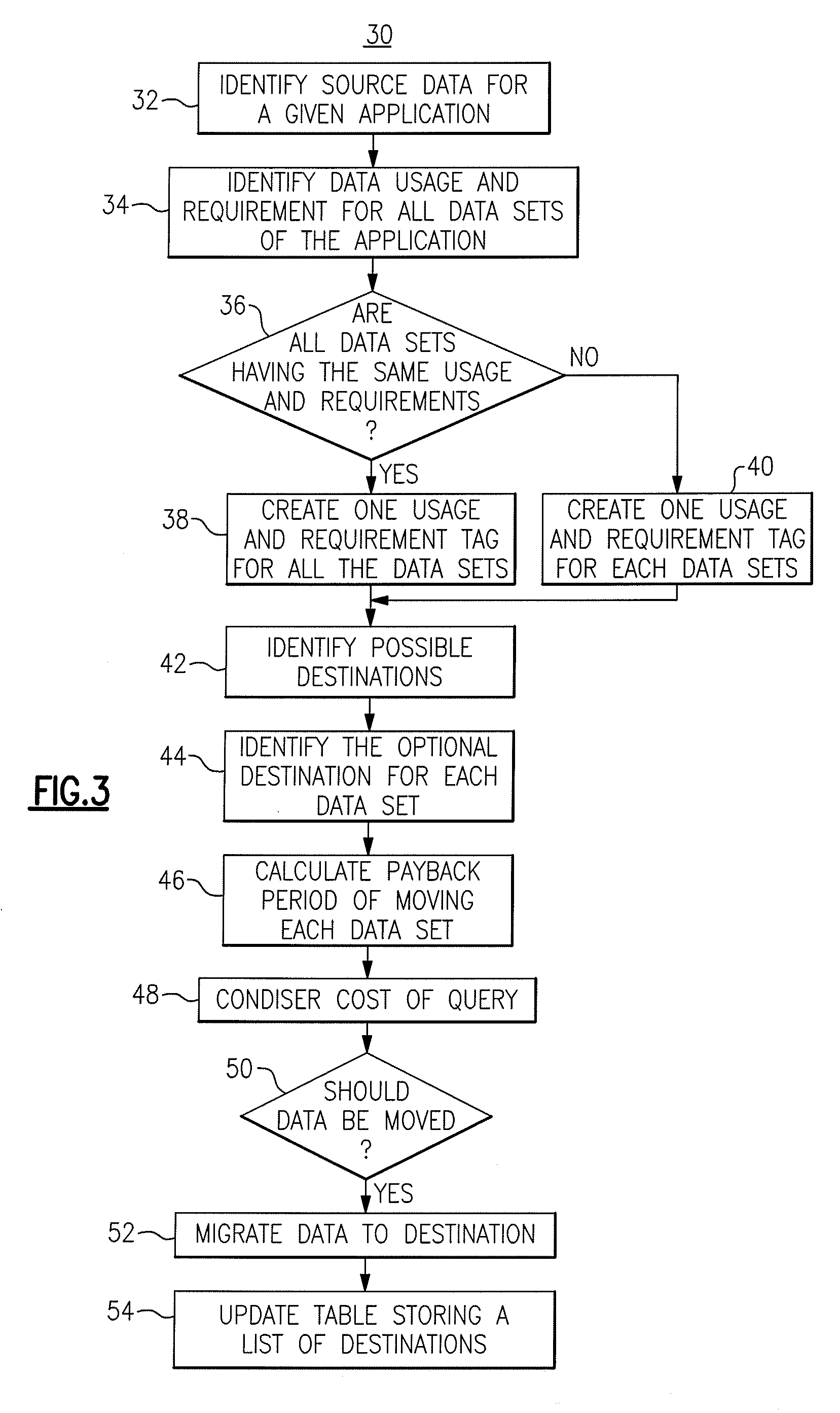
[0026]In this example, a company's Financial Portal application data is being reviewed to determine if it can be migrated for a cost savings benefit. The Portal contains two databases, a user information database that is used for authentication and authorization (DB_UserInfo) and a financial database that contains various financial data of the company (DB_Financial). The DB_UserInfo database is being used daily by about 300 financial users throughout the company, across the country during office hours. It is assumed that the DB_UserInfo database contains only two Tables, Table_UserLoginInfo and Table_AccessControl. A data usage and requirement tag is created for the entire database by the following queries:

[0027]1. Time restriction: No

[0028]2. Usage frequency: Daily

[0029]3. Expected access time: Within x amount of seconds

[0030]4. Geography of major users: Americas

[0031]5. Peak hours of access: Morning (8 am-6 pm EST)

[0032]6. Amount of concurrent users during peak hours of access: 30...

example 2

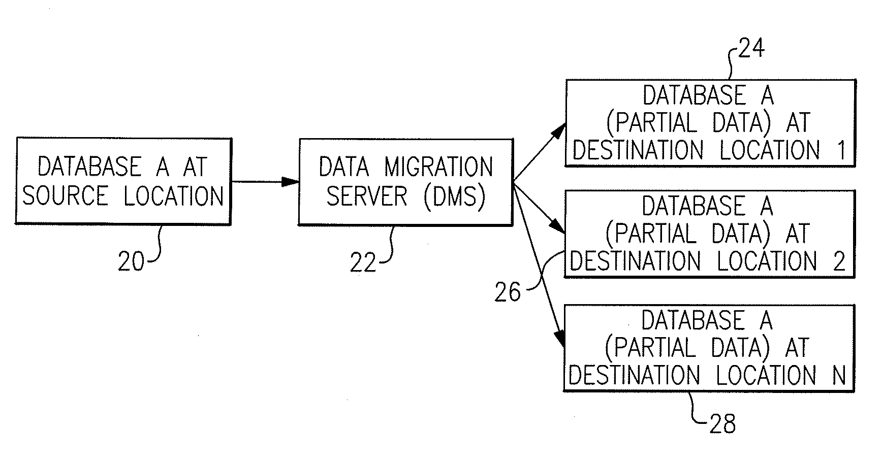
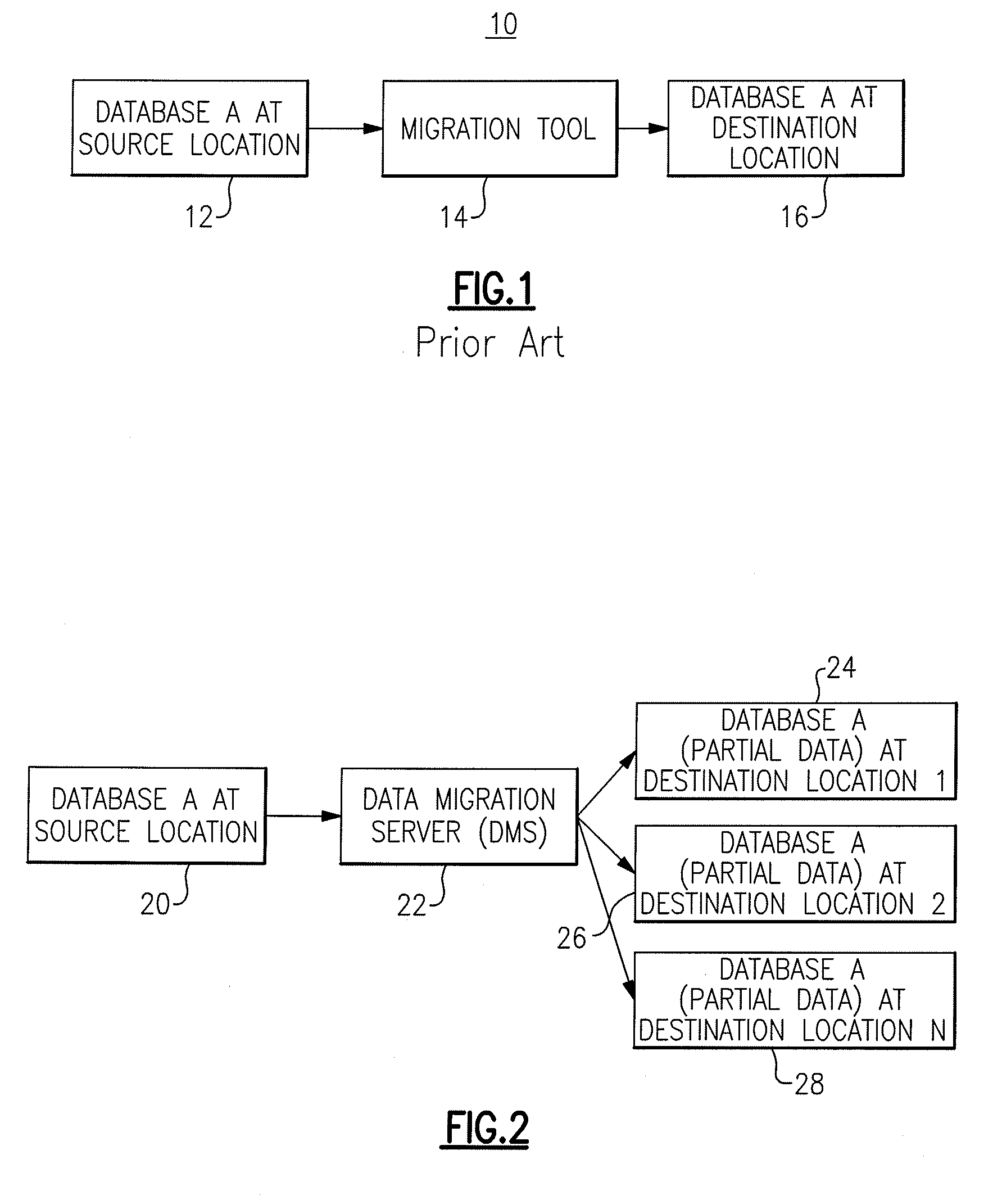
[0045]The Financial Portal in Example 1 above is used in this example. In viewing Tables 3 and 4 above, the tag created for DB_UserInfo in Example 1 above may fit into three destination databases. NAS001 currently stores an email database DB_Mail001 that is used by 2000 users in the United States on a daily basis between 8 am and 6 pm EST. Although the power used per operation is fairly low (425 watts per operation), this location may not be the most desirable for storing DB_UserInfo because DB_UserInfo has 300 users accessing the database within the same time slot from 8 am to 6 pm, and users are expecting the response time to be within a few seconds. NAS003 may be more desirable by comparison. Even though it has an email database that is used by users in the same time slot, the number of users is much less in NAS003 than in NAS001. A third candidate choice is NAS002, since the users in NAS002 access the data from 8 am to 6 pm Japan time, which is about 7 pm to 5 am EST. The server...

example 3

[0046]In this example, the database DB_Financial of the Financial Portal is evaluated for migration to the best candidate destination database. It has three datasets with different tags. The VIEW_DailyManagerialTasks is accessed daily only during the morning when the managers would like to see any pending tasks that need their approval. The three candidate choices for this dataset are as follows. The first is NAS001, which may not be a good choice since it already has an email database that is used by 2000 users in the same geographic area for the same time slot. The second option is NAS003, which has two applications (an email database and potentially, the Finance Portal's DB_UserInfo) that use the same time slot. The third choice is NAS002 because it will not conflict with the users that are using the email database (DB_Mail002) due to the time slot it is being used (7 pm-5 am EST). Also, the managers in the United States may not be upset if the data retrieval speed is a few secon...


PUM


Abstract

A method and system for migrating source data from a source database to a destination database based on energy efficiency and conservation. A migration server evaluates the source data for usage and requirements and defines data usage and requirement tags for the source data. The source data is disaggregated into one or more source data sets based on the data usage and requirement tags. The migration server then identifies candidate destinations for the source data, wherein each candidate destination has stored data identified with usage and requirement tags. The data migration server compares the first usage and requirement tags of the source data with the second usage and requirement tags of the stored data and identifies an optimal destination database based on the comparing step. The data migration server migrates the source data to the optimal destination database.

Description

BACKGROUND OF THE INVENTION[0001]The present invention relates generally to energy efficiency across the data center, and more particularly to the migration of data based on power consumption.[0002]Energy efficiency across the entire data center is becoming a top concern for corporations around the world. This problem requires consideration of all energy efficiency components of the data center, from component levels through server and system levels, and concluding with the complete data center. At the system level, storage devices are an extremely important part of the equation, which needs to be analyzed. Disk systems can require substantial amounts of power to operate and cool, and in many cases, can require more power than the server itself.[0003]Data migration is the process of transferring data between storage types, formats or computer systems. Data migration is usually performed programmatically to achieve an automated migration, freeing up human resources from tedious tasks...

Claims


Application Information

Patent Timeline
Patent Type & Authority Applications(United States)
IPC IPC(8): G06Q10/00G06F17/30
CPCG06F3/0605G06F3/0625G06F3/0649Y02B60/188G06F17/303G06Q10/0637Y02B60/1246G06F3/067G06F16/214Y02D10/00
Inventor HAMILTON, II, RICK A.LI, JENNY S.SALVE, VIVEKSAND, ANNE R.STAHL, ELISABETH R.
Owner IBM CORP
Why Eureka
Try Eureka