Parallel Run-Time Rendering Debugger

a run-time rendering and debugger technology, applied in the field of parallel run-time rendering debugger, can solve the problem of requiring a large amount of computational work

Inactive Publication Date: 2009-11-12
MICROSOFT TECH LICENSING LLC
View PDF29 Cites 7 Cited by
  • Summary
  • Abstract
  • Description
  • Claims
  • Application Information

AI Technical Summary

Benefits of technology

[0005]The debugging works by dynamically modifying the application being debugged. It replaces the visual output of the selected code with an intermediary value from within the code, based on a selection in the user interface. In this way, multiple executions of an algorithm, such as a pixel shader executed over many pixels, can be debugged at once by having each pixel output an intermediary value generated during its rendering, thus achieving massively parallel debugging with almost no performance impact on the application. The process of dynamic modification can be done at interactive rates, allowing a user to efficiently browse through large amounts of rendering code, quickly seeing the values read and written at each point. The tool provides a huge usability jump over previous debugging methods that generally required the application to be paused and executed step-by-step, allowing the debugger time to read the values it is looking for and display them to the user in a separate interface. This pitfall is avoided by having the debug output flow into existing display channels.
[0008]The user interface graphs out the code as a dependency tree, allowing the user to quickly see not only the values generated in the code, but also to see for a particular value which parts of the code contributed to it, and which were affected by it. In this way, the user is able to quickly determine how the code is interrelated.

Problems solved by technology

A common optimization exposed by the present method is uncovering an instruction that outputs the same value across an entire wireframe, but that requires a large amount of computational work.

Method used


Image

  • Parallel Run-Time Rendering Debugger
  • Parallel Run-Time Rendering Debugger
  • Parallel Run-Time Rendering Debugger

Examples


Embodiment Construction

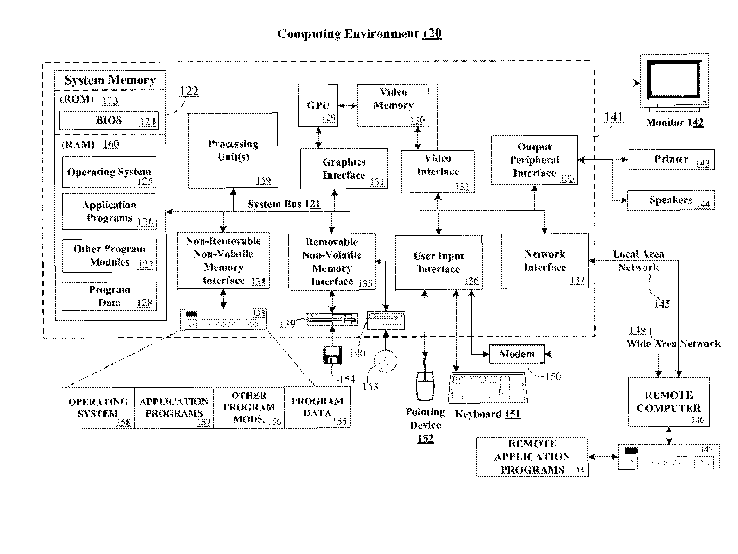
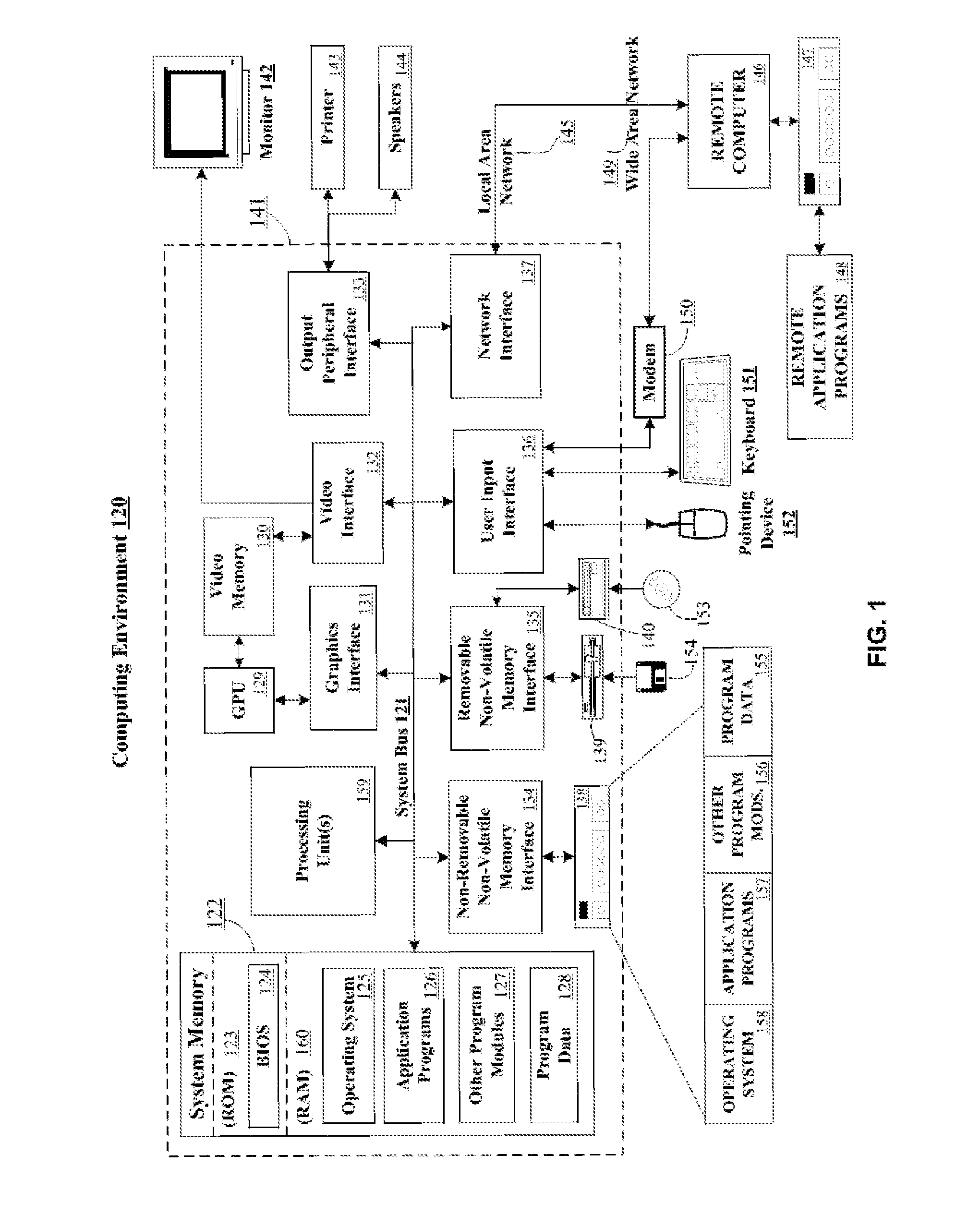
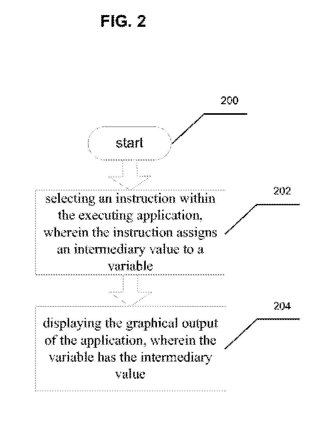
[0016]Certain specific details are set forth in the following description and figures to provide a thorough understanding of various embodiments. Those of ordinary skill in the relevant art will understand that they can practice other embodiments without one or more of the details described below. While various methods are described with reference to steps and sequences in the following disclosure, the description as such is for providing a clear implementation of embodiments of the invention, and the steps and sequences of steps should not be taken as required. FIG. 1 illustrates an operating environment in which operating procedures may be performed. FIGS. 2-3 depict example operating procedures. FIG. 4. depicts an example user interface for using the method of FIG. 3, which includes the results of those operations.

[0017]FIG. 1 illustrates an exemplary system for implementing aspects of the presently disclosed subject matter, including a general purpose computing device in the for...


PUM


Abstract

Systems and methods are disclosed for debugging the graphical output of a software program. This may be achieved both by displaying the graphical output of the software program at intermediary stages of the graphical rendering process, and by visually representing the interdependencies found within the software code of the program.

Description

BACKGROUND OF THE INVENTION[0001]In graphical software applications, the graphical rendering code, which writes values into a display or intermediary buffer for users to see, is often complicated, hard to understand and even harder to debug, or to visualize the intermediary steps and results thereof. The graphical rendering code can be difficult to debug because it is executed very frequently (for example, texture blending code is often executed on a per-pixel basis, which requires millions of evaluations per second, spread across the output display), or because visual effects are time-based, so properly debugging them requires analysis of those millions of evaluations while the application is running.[0002]Thus, the debugging process of graphical rendering code can be improved upon by allowing for debugging a great number of values at once, in a visual manner. Some of these techniques may be generalized to aid debugging computer code in general.SUMMARY OF THE INVENTION[0003]In exam...

Claims


Application Information

Patent Timeline
IPC IPC(8): G06F9/44
CPCG06F11/362
Inventor GESELOWITZ, LEWEY ALEC
Owner MICROSOFT TECH LICENSING LLC
Why Eureka
Try Eureka