Wet/dry cooling tower and method

a technology of wet/dry cooling tower and cooling tower, which is applied in the direction of carburetizing air, lighting and heating apparatus, separation processes, etc., can solve the problems of dry cooling being less efficient than wet cooling, water vapor may exit the tower in the form of visible water vapor or plume, and being considered undesirable, so as to reduce the effect of the plum

Active Publication Date: 2009-11-19
SPX COOLING TECH
View PDF17 Cites 28 Cited by
  • Summary
  • Abstract
  • Description
  • Claims
  • Application Information

AI Technical Summary

Benefits of technology

[0008]Some embodiments according to the present invention provide a cooling tow

Problems solved by technology

In some cases, the water vapor may exit the tower in the form of a visible water vapor or plume which is sometimes considered undesirable depending on location and other circumstances.
However, depending on the operating and ambient temperatures, in some cases dry cooling can be less efficient than wet cooling in terms of the energy consumption and/or construction expense of the tower.
Moreover, dry cooling tends in some circumstances to be more dep

Method used


Image

  • Wet/dry cooling tower and method
  • Wet/dry cooling tower and method
  • Wet/dry cooling tower and method

Examples


Embodiment Construction

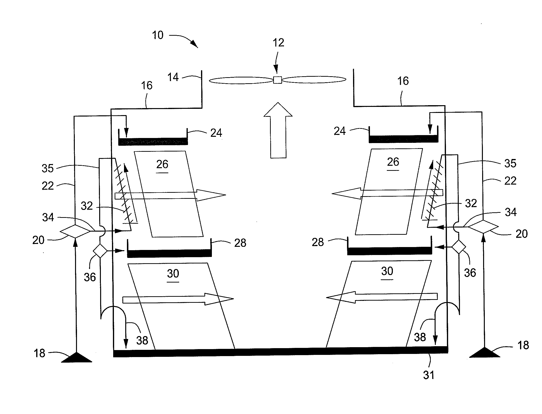
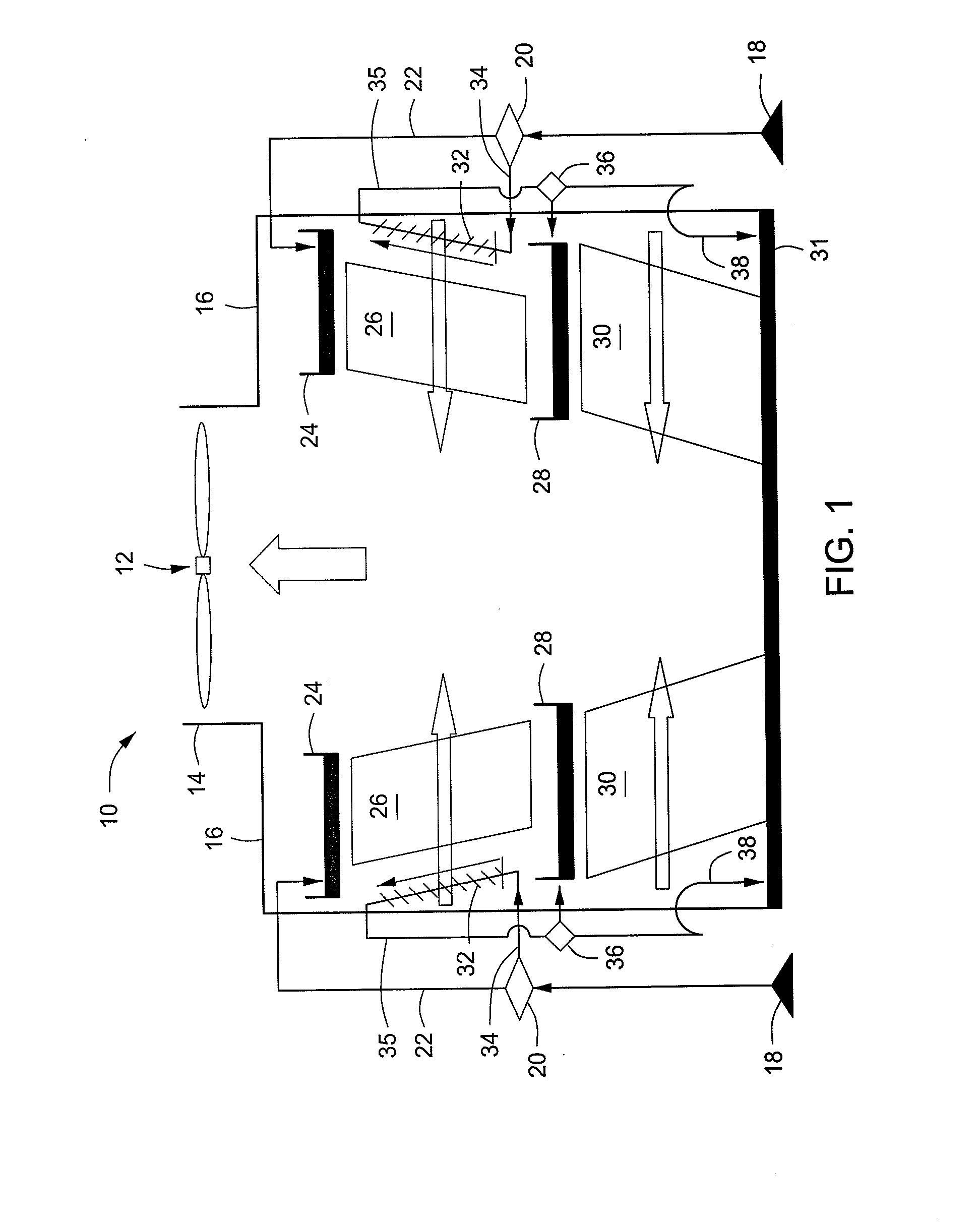
[0022]Some embodiments according to the invention provide a cooling tower and method that can provide desirable efficiencies while also reducing plume. Examples of preferred embodiments will now be described with reference to the drawing figures, in which like reference numbers refer to like parts throughout.

[0023]FIG. 1 is a schematic diagram of a first preferred embodiment of the invention. In this embodiment, a generally or completely symmetrical structure is provided, where air enters the side of the tower 10, passes through various media, as shown, and exits out the top of the tower 10. The cooling tower 10 includes a fan 12 which draws air out of an air outlet structure 14. The tower 10 also has an internal framework (not illustrated) which supports the various components that will be discussed. The tower 10 may have a basin cover 16 forming a roof of the tower, or may simply have an open roof. Turning next to the water flow, relatively warm water or other liquid to be cooled ...


PUM

PropertyMeasurementUnit
Fractionaaaaaaaaaa
Heataaaaaaaaaa

Abstract

An atmospheric cooling tower apparatus includes a housing structure having an air inlet and an air outlet, a first evaporative heat transfer media disposed in the housing, and a closed coil heat transfer media disposed in the housing. A water distribution assembly is disposed above the evaporative heat transfer media and configured to distribute water onto the evaporative fill heat transfer fill media. A collection basin is disposed beneath the evaporative heat transfer media configured to collect water that has passed through the evaporative heat transfer media. A first control valve controls an inflow of water to supply water to one or both of the evaporative heat transfer media and the closed coil heat transfer media. The closed coil heat transfer media and the evaporative heat transfer media are disposed laterally next to each other.

Description

FIELD OF THE INVENTION[0001]The invention pertains generally to the field of cooling towers which cool a warm liquid by interaction with cooler ambient air.BACKGROUND OF THE INVENTION[0002]Cooling towers are in wide use in industry. These towers are typically used to receive a warm or relatively warm fluid, such as, for example, warm water from an industrial operation. The warm water is passed through the tower and, by a heat exchange interaction with ambient air that is cooler than the water, the water is cooled and then can be discharged or returned to the industrial operation. Cooling towers include various configurations such as cross-flow cooling towers in which the air enters from a side of the tower and passes generally laterally horizontally across the fill media, and also counterflow cooling towers where the air generally enters beneath the fill material and is drawn upward through the fill material.[0003]There are at least two general types of such cooling towers. The firs...

Claims


Application Information

Patent Timeline
IPC IPC(8): F28D5/00
CPCF28C1/04F28C1/14Y10S165/90Y10S261/11Y10S261/77F28F27/003Y02B30/70
Inventor HENTSCHEL, GREGORY P.MAURER, SCOTT T.
Owner SPX COOLING TECH
Why Eureka
Try Eureka