Semi-symmetric switching

a switching element and semi-symmetric technology, applied in the direction of electronic commutation motor control, electric/dynamo-electric converter control, electric/dynamo-electric converter starters, etc., can solve the problems of switching elements driven by pwm signals to be excessively affected, switching elements to deteriorate at different rates, and different in their performan

Active Publication Date: 2022-11-01
MIRKA OY
View PDF5 Cites 0 Cited by
  • Summary
  • Abstract
  • Description
  • Claims
  • Application Information

AI Technical Summary

Benefits of technology

[0023]When an electric path is formed between the terminals of the DC power source through switching elements which are ON, a voltage is obtained between separate points on phase windings of the brushless motor. The obtained voltage leads to a current flowing through the switching elements which are ON and the phase windings between these points, which, in turn, leads to a magnetic field being generated in the motor. The generated magnetic field interacts with the rotor (for example with a magnetic field generated by permanent magnets on the rotor), causing the rotor to operate as desired.
[0064]Hence, the above-described power tools, controllers, methods, computer programs and non-transitory storage mediums, it is possible to provide an electric motor control allowing for the power losses to be distributed on switching elements in a driver circuit and having a desirable overall efficiency whilst operating the motor according to a desired operation.

Problems solved by technology

However, asymmetric switching causes the switching element driven by the PWM signal to be excessively affected, because it suffers from larger switching losses, and consequently from a higher temperature increase than the other switching element in the pair.
This may lead to the switching elements to deteriorate at different rates, or differ in their performance.
Additionally, conduction losses in the switching elements and its diode or body diode are also unequally affected.
However, symmetric switching requires both switching elements to be repeatedly switched ON and OFF, leading to a higher total power loss and therefore a significantly reduced overall efficiency which is undesirable.
At the same time, powered devices emit electromagnetic energy when operating, which can negatively affect surrounding equipment, by causing electromagnetic interference, for example.
With the above power tool comprising the controller, the first and second switching elements are not switched at the same time, therefore the switching losses occurring in each switching element are limited, and the efficiency of the system is maintained when compared, for example, to an asymmetric switching scheme, or even improved when compared, for example, to a symmetric switching scheme.
Additionally, because the switching elements are switched alternately, or in turn, the switching losses are distributed between the switching elements.
When considering both the first and second commutation periods, the switching losses are distributed between the two switching elements, such that neither switching element is disproportionately affected.
With the above controller, the first and second switching elements are not switched at the same time, therefore the switching losses occurring in each switching element are limited, and the efficiency of the system is maintained when compared, for example, to an asymmetric switching scheme, or even improved when compared, for example, to a symmetric switching scheme.
Additionally, because the switching elements are switched alternately, or in turn, the switching losses are distributed between the switching elements.

Method used


Image

  • Semi-symmetric switching
  • Semi-symmetric switching
  • Semi-symmetric switching

Examples


embodiment 1

[0101]FIG. 4 shows the control signals C1 and C2 generated by the controller 100 for controlling switching elements to be alternately switched, according to an embodiment.

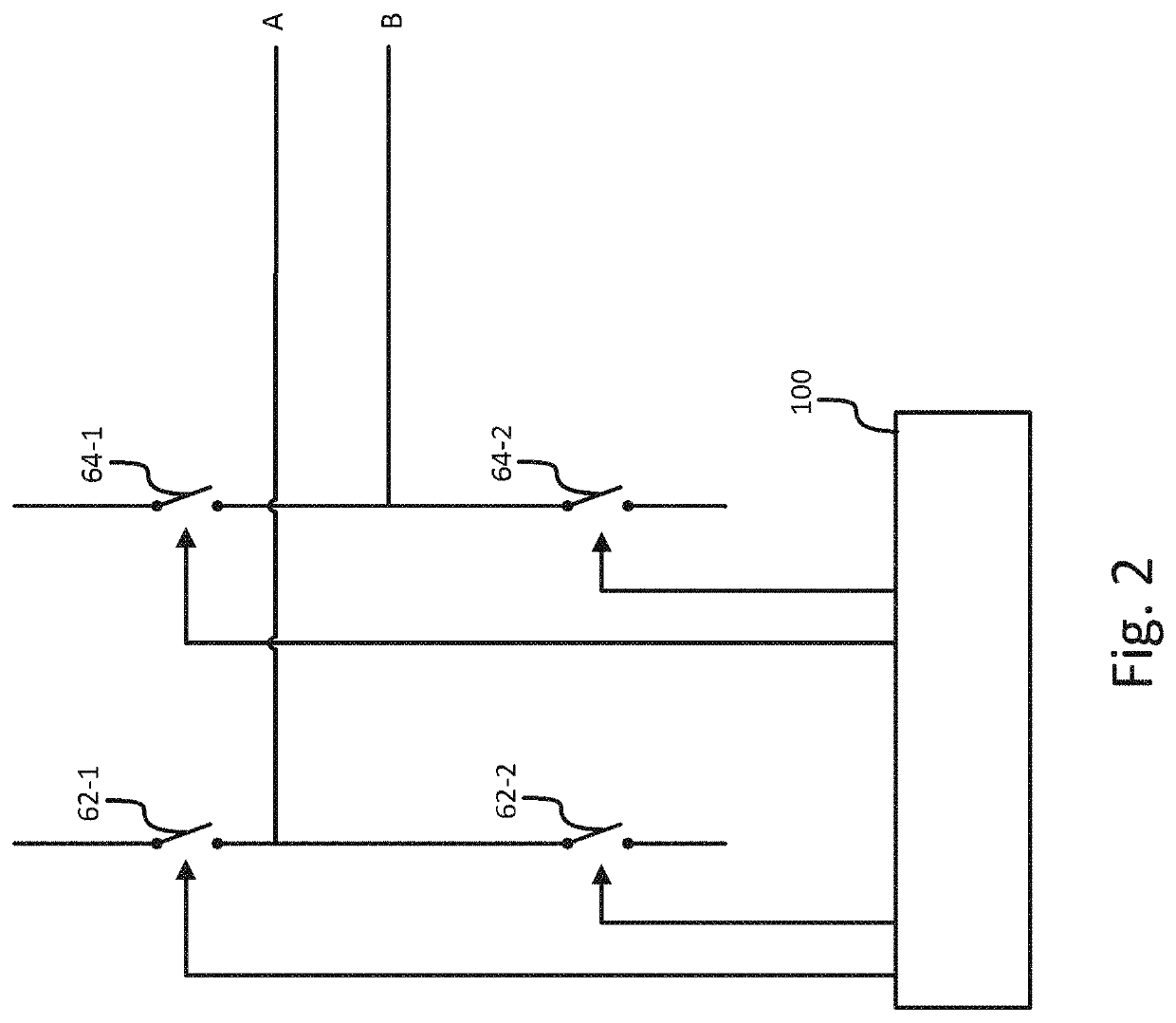
[0102]In the present embodiment, switching elements are metal-oxide FETs, MOSFETs, and the controller 100 is electrically coupled to the gate electrode of each MOSFET. Controller 100 generates control signal C1 for controlling MOSFET 62-1 and control signal C2 is for controlling MOSFET 64-2.

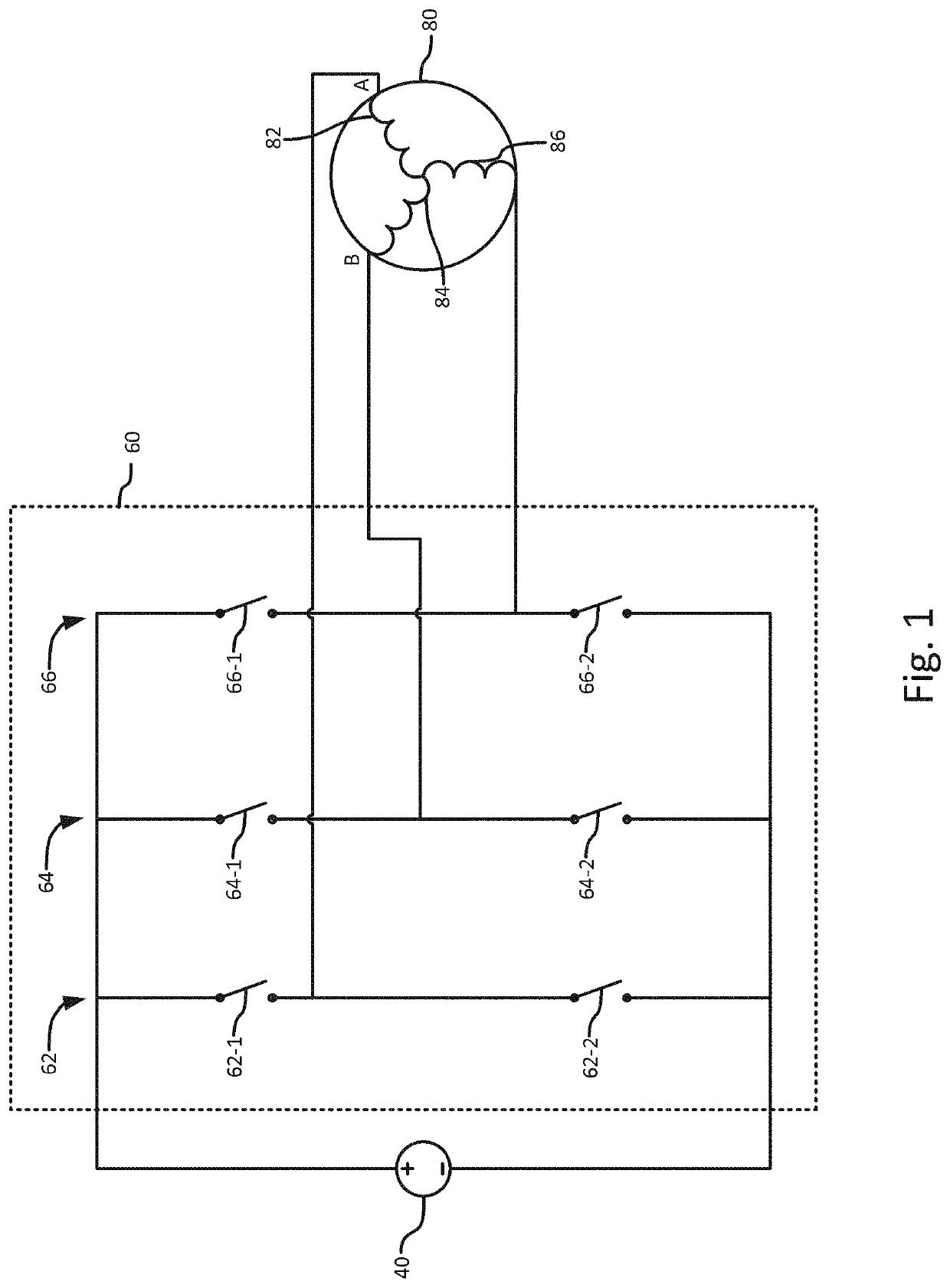
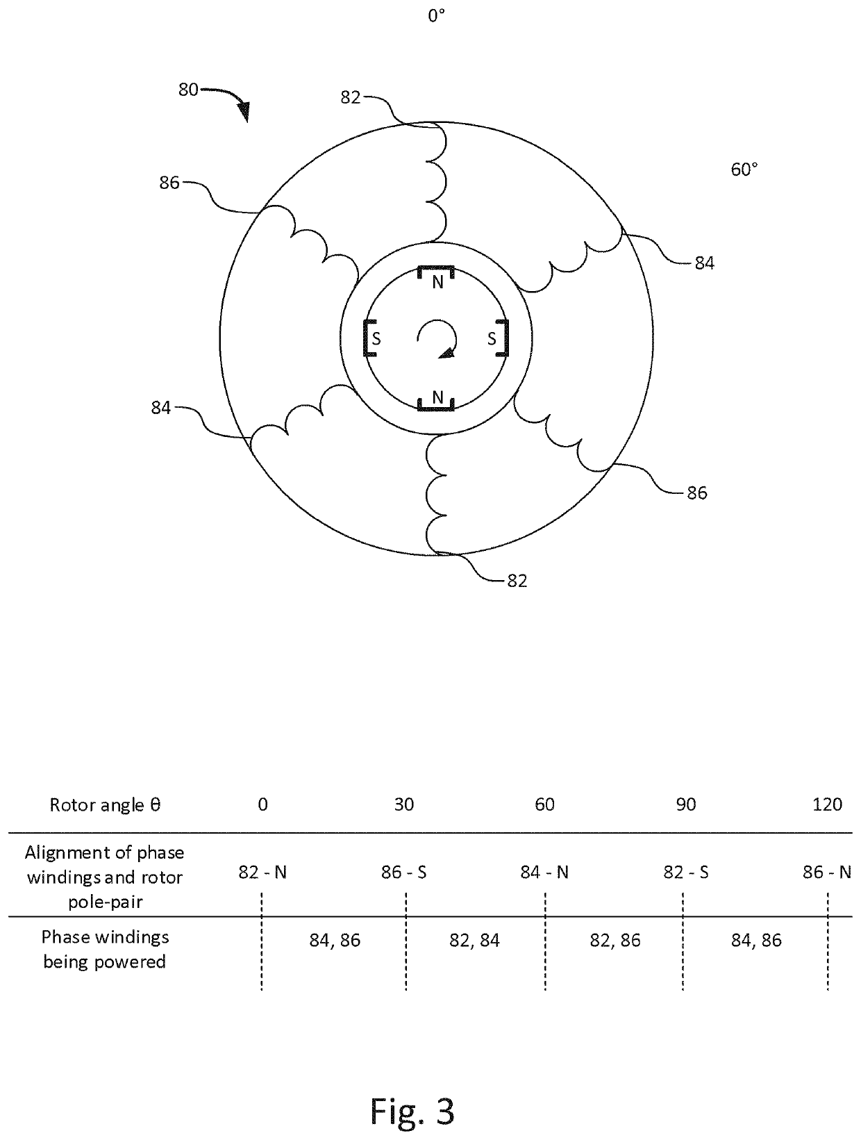
[0103]Referring back to FIG. 3, these control signals may, for example, be generated while the rotor angle is between 30° and 60°, and phase windings 82 and 84 are powered. Controller 100 also generates control signals for controlling the remaining switching elements of the driver circuit 60, but the representation of these control signals is omitted for simplicity.

[0104]FIG. 4 also shows the voltage Vab obtained between points A and B in the phase windings of the motor 80, based on the state of MOSFETs 62-1 and 64-2.

[0105]In th...

embodiment 2

[0115]FIG. 5 shows control signals C1 and C2 generated by the controller 100 for controlling switching elements 62-1 and 64-2 so as to alternately switch switching elements 62-1 and 64-2 during the same switching period, according to an embodiment.

[0116]More specifically, switching elements 62-1 and 64-2 are turned ON during a commutation period of the motor

[0117]FIG. 5 also shows the voltage Vab obtained between points A and B in the phase windings of the motor 80.

[0118]For example, switching element 62-1 is turned ON at the start of a switching period Ts1 and switching element 64-2 is turned OFF near a central point of switching period Ts1. Then, switching element 64-2 is turned ON at the start point of the switching period Ts2 following Ts1, and switching element 62-1 is turned OFF near a central point of switching period Ts2.

[0119]The control signals C1 and C2 allow for a pulsing voltage Vab to be obtained, each pulse of voltage Vab being between a rising edge of one of the cont...

embodiment 3

[0129]Referring now to FIGS. 7a to 7c, an embodiment will be described.

[0130]FIG. 7a shows a controller 200 and two switching element pairs 62 and 64 of driver circuit 60.

[0131]In the present embodiment, driver circuit 260 includes MOSFETs as switching elements. MOSFETs 262-1 and 62-2 of the first MOSFET pair 262, and MOSFET 264-2 of the second MOSFET pair 264 are each provided with a sensor 202-1 to 202-3, to obtain information indicating a state of the corresponding MOSFET.

[0132]In this embodiment, sensor 202-1 and 202-2 are arranged to obtain information indicating a temperature of MOSFET 262-1 and 264-2, respectively.

[0133]The controller 200 is arranged to obtain information indicating a state of an MOSFET from at least one of sensors 202-1 or 202-2.

[0134]Based on the obtained information, the controller 200 may determine that one of MOSFET 262-1 and MOSFET 264-2 is affected by the switching distinctively more than the other switching element. The controller may determine to swi...


PUM


Abstract

A power tool with a direct current, DC, power source comprising a controller for controlling a driver circuit driving a brushless motor in a power tool, the driver circuit being coupled to a direct current, DC, power source and including a first switching element pair coupled to a first phase winding of the brushless motor and a second switching element pair coupled to a second phase winding of the brushless motor; and the controller being arranged to alternately switch a first switching element of the first switching element pair and a second switching element of the second switching element pair, wherein the first switching element and the second switching elements are coupled to a respective terminal of the DC power source. A power tool comprising such a controller, and a method of controlling a driver circuit driving a brushless motor in a power tool.

Description

CROSS REFERENCE TO RELATED APPLICATIONS[0001]This Application is a national stage filing under 35 U.S.C. 371 of International Patent Application Serial No. PCT / EP2018 / 065972, filed Jun. 15, 2018, entitled “SEMI-SYMMETRIC SWITCHING”, the content of which is incorporated herein by reference in its entirety.TECHNICAL FIELD[0002]The present disclosure generally relates to electric motor control, and more particularly to a power tool, a controller for controlling a driver circuit used to drive an electric motor, a method of controlling a driver circuit, a computer program and a non-transitory storage medium.BACKGROUND ART[0003]Many powered devices, that is, devices being supplied with electric power to operate, use electric motors to function. Powered devices are advantageous because they rely on power supplied by an electric source, either alternating current (AC) or direct current (DC), which is easily generated and controllable.[0004]In powered devices, the operation of an electric mo...

Claims


Application Information

Patent Timeline
Patent Type & Authority Patents(United States)
IPC IPC(8): H02P1/00H02P27/08H02P6/08
CPCH02P27/085H02P6/085H02P2207/05H02P6/08
Inventor NORDSTRÖM, CAJSÖDERGÅRD, TOMAS
Owner MIRKA OY
Why Eureka
Try Eureka