
Shielding assembly

a technology of shielding and components, applied in the direction of cooling/ventilation/heating modifications, screening rigid plastic containers, and modifications by conduction heat transfer, etc., can solve the problem that typical shielding does not have the function of cooling components

Inactive Publication Date: 2009-11-19
FIH (HONG KONG) LTD
View PDF3 Cites 12 Cited by
  • Summary
  • Abstract
  • Description
  • Claims
  • Application Information

AI Technical Summary

Benefits of technology

[0005]To attenuate EMI effects, shielding can having the capability of absorbing and / or reflecting EMI energy may be employed to confine the EMI energy within a source device, and to insulate that device or other “target” devices from other source devices. Such shielding is provided as a barrier which is interposed between the source and the other devices, and typically is configured as an electrically conductive and grounded housing which encloses the device, or as a “can” which covers a discrete component or component of the device. The housing or can may be made of metal such as steel, aluminum, or magnesium, or alternatively, of plastic or other polymeric materials which is filled to be electrically-conductive. However, the typical shielding has not the function in the form of cooling the components.

Problems solved by technology

However, the typical shielding has not the function in the form of cooling the components.

Method used


Image

  • Shielding assembly
  • Shielding assembly
  • Shielding assembly

Examples


Embodiment Construction

[0011]Exemplary embodiments will now be described in detail below and with reference to the drawings. The shielding assembly is suitably assembled within the portable electronic device, such as the mobile phone, the personal digital handset, or the like.

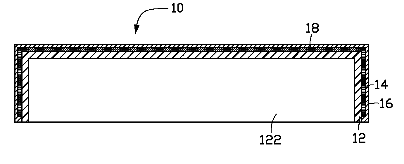
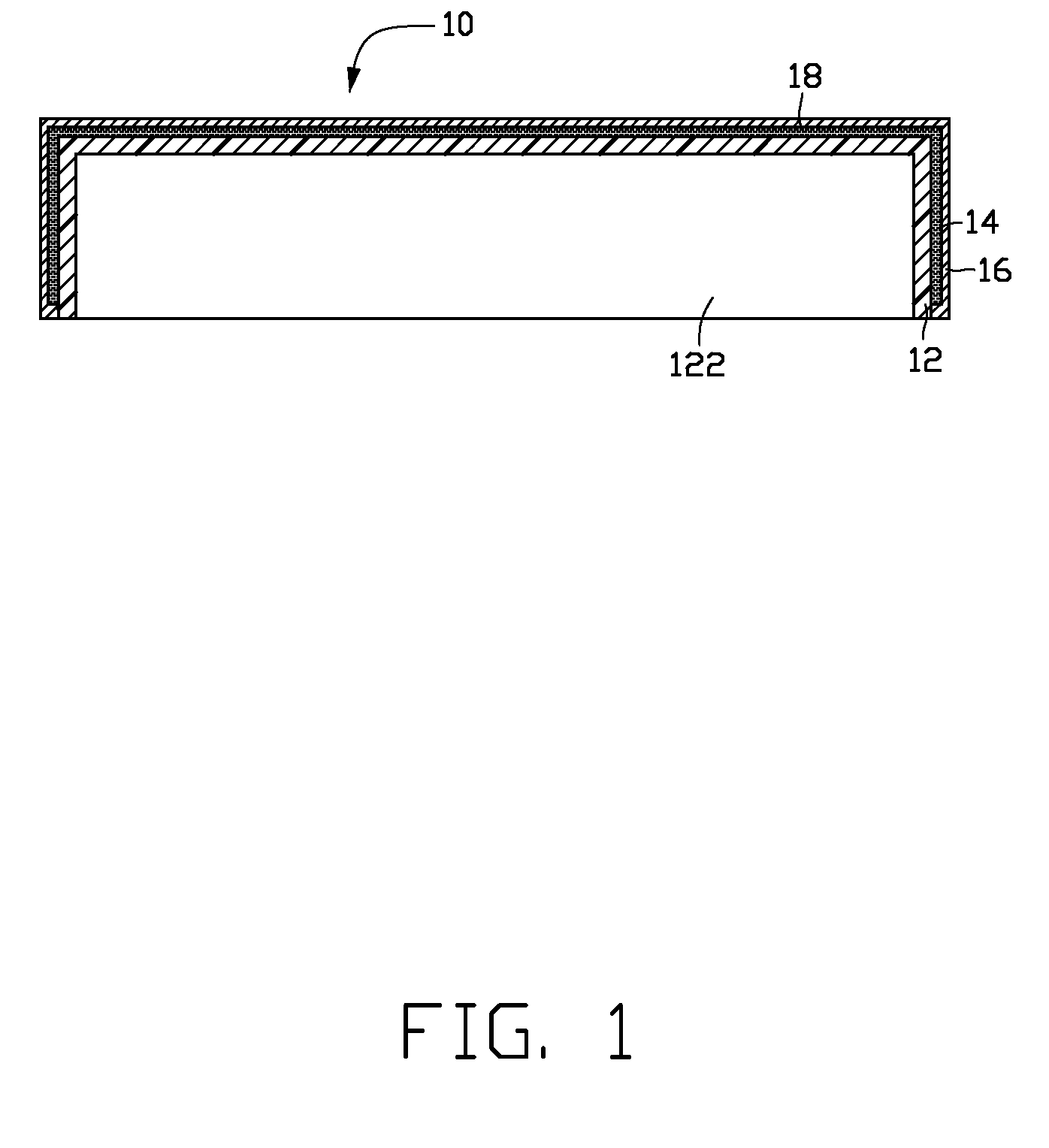
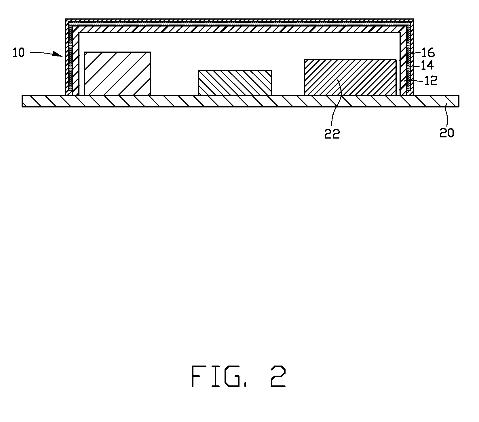
[0012]Referring to FIG. 1, the shielding assembly 10 includes a flexible plastic layer 12, a coolant 14, and a metal foil 16. Referring to FIG. 2, the plastic layer 12 encloses a room 122 for accommodating electronic components 22 on a circuit board 20. The metal foil 16 is mounted (e.g., adhered) to the plastic layer 12, and a chamber 18 is formed between the metal foil 16 and the plastic layer 12. The chamber 18 is for accommodating the coolant 14.

[0013]The plastic layer 12 may be made of one or more materials selected from a group consisting of polyvinyl chloride (PVC), polycarbonate, polystyrene, and any other thermoplastic resins. The metal foil 16 is made of metal material, such as iron or aluminum.

[0014]The coolant 14 may be m...


PUM


Abstract

A shielding assembly (10) for electronic device is provided. The shielding assembly (10) comprises a plastic layer (12), a metal foil (16) mounted to the plastic layer (12), and a coolant (14) is formed between the plastic layer (12) and the metal foil (16). An electronic device using the shielding assembly is also provided.

Description

BACKGROUND[0001]1. Field of the Invention[0002]The exemplary invention relates to shielding assemblies and, particularly to shielding assemblies used for portable electronic devices.[0003]2. Description of Related Art[0004]The operation of portable electronic devices such as mobile telephone, televisions, radios, computers, medical instruments, business machines, communications equipment, and the like is attended by the generation of electromagnetic radiation within the electronic circuitry of the equipment, and is termed “electromagnetic interference” or “EMI” as being known to interfere with the operation of other proximate electronic devices.[0005]To attenuate EMI effects, shielding can having the capability of absorbing and / or reflecting EMI energy may be employed to confine the EMI energy within a source device, and to insulate that device or other “target” devices from other source devices. Such shielding is provided as a barrier which is interposed between the source and the ...

Claims


Application Information

Patent Timeline
IPC IPC(8): H05K9/00
CPCH05K9/0045H05K7/20509
Inventor HSIEH, HSING-YUAN
Owner FIH (HONG KONG) LTD
Learn More