Machine for orienting and aligning articles

Inactive Publication Date: 2009-11-19
MARTI SALA JAIME +1
View PDF7 Cites 8 Cited by
  • Summary
  • Abstract
  • Description
  • Claims
  • Application Information

AI Technical Summary

Benefits of technology

[0005]A machine for orienting and aligning articles which is easy and inexpensive to construct and capabl

Problems solved by technology

However, the implementation of the rotating cylindrical wall and the stationary bottom and ramp involves a relativ

Method used


Image

  • Machine for orienting and aligning articles
  • Machine for orienting and aligning articles
  • Machine for orienting and aligning articles

Examples


Embodiment Construction

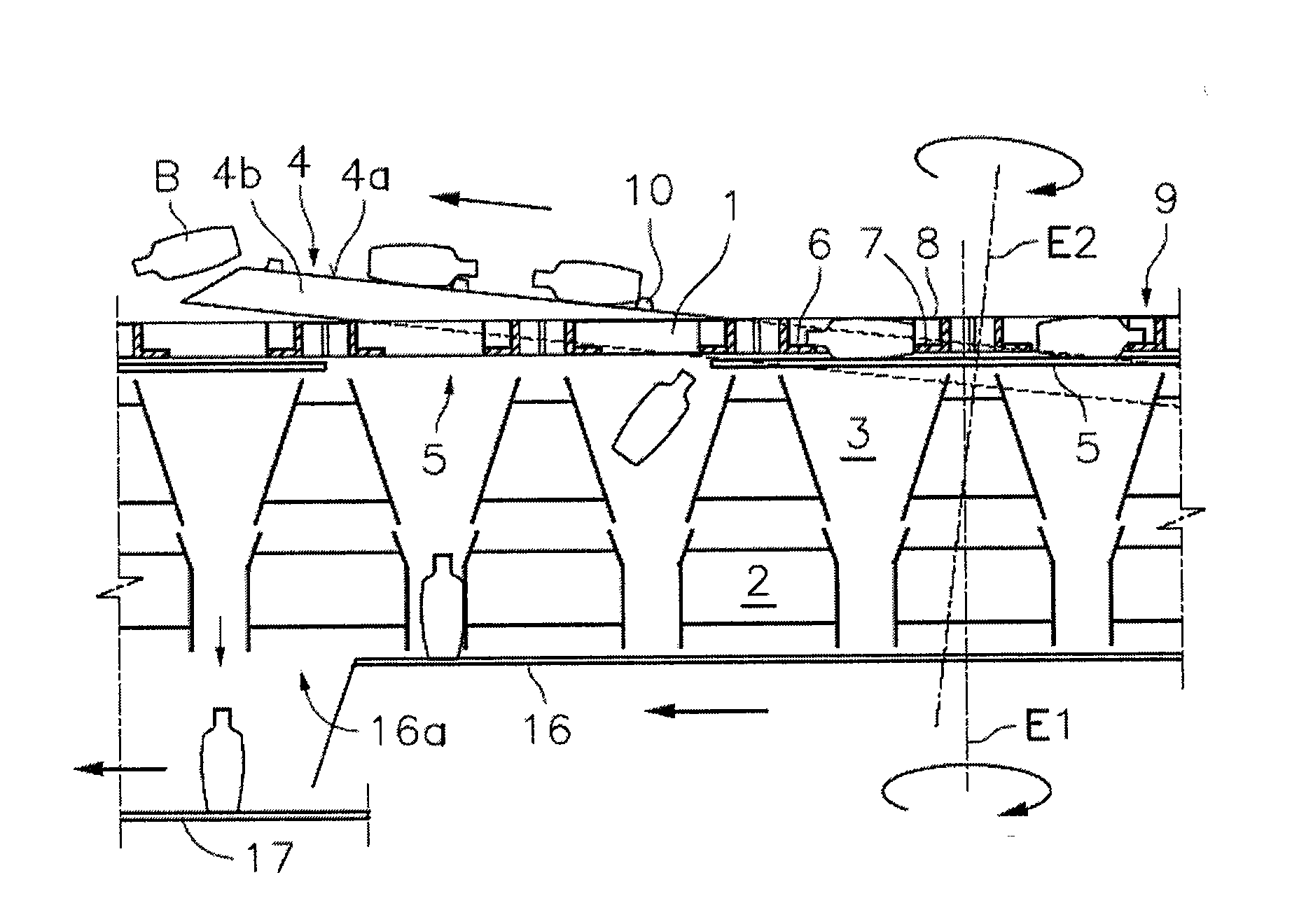
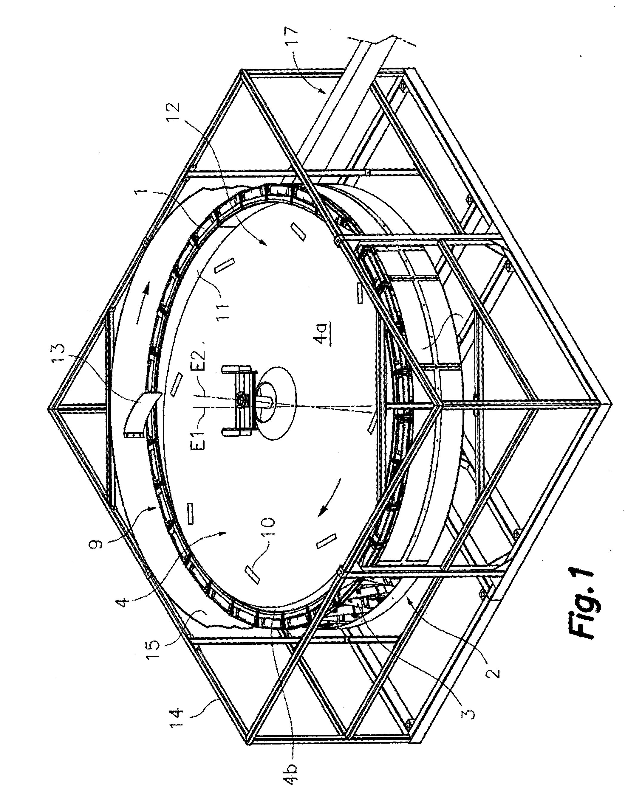
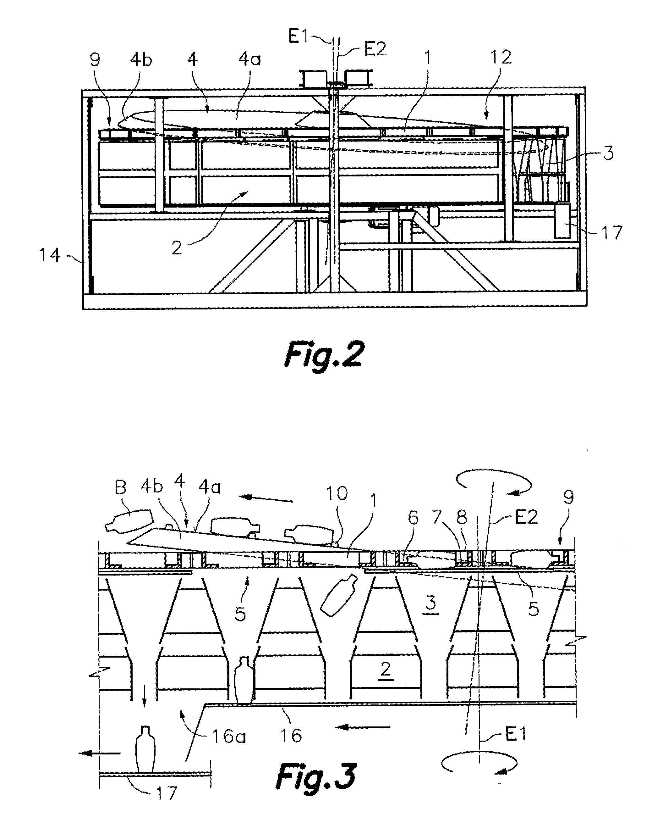
[0012]Referring first to the Figures in general, the machine for orienting and aligning articles comprises, according to an embodiment, a frame 14 supporting a rotary structure 2 assembled such that it can rotate about a vertical axis E1. The mentioned rotary structure 2 defines a substantially horizontal perimetric ring 9 surrounding a receptacle 12 serving for the accumulation of the articles to be oriented and aligned in a disordered situation. In the rotary structure 2 there is fixed a plurality of orientation cavities 1 distributed along said perimetric ring 9 such that they are moved along a closed circuit by the rotary structure 2 upon rotating. Each of said orientation cavities 1 is sized to house only one of the articles in a lying position and in any of two opposite positions. The orientation cavities 1 have an upper inlet for receiving articles and an open bottom for the passage of the articles. The upper inlets of the orientation cavities 1 are arranged in an aligned man...


PUM


Abstract

A rotary structure carries cavities with an upper inlet for receiving articles and an open bottom for dropping articles distributed along a closed circuit, and funnel-shaped conduits, each of which is located below a respective cavity to receive an article therefrom, means for temporarily supporting the articles in the cavities and dropping them into the corresponding conduits in a site of the closed circuit, and support elements in each cavity to cooperate with parts of the article when the latter falls in order to confer to it a predetermined orientation inside the conduit. The cavities have their inlets in a perimetric ring surrounding a receptacle for the accumulation of the articles on a bottom formed by a rotating disk the peripheral edge of which reaches, upon rotating, a level above the perimetric ring.

Description

TECHNICAL FIELD[0001]The present invention relates to a machine for orienting and aligning articles, such as empty plastic bottles or containers.BACKGROUND OF THE INVENTION[0002]Machines for orienting and aligning articles such as empty plastic bottles or containers are known, which machines comprise a plurality of orientation cavities associated to a rotary structure and distributed along a perimetric ring thereof, such that said orientation cavities rotate with the rotary structure in a closed circuit. The orientation cavities are provided with an upper inlet for receiving articles and with an open bottom for the passage of the articles. The rotary structure has a plurality of funnel-shaped alignment conduits, each of which is arranged below a respective orientation cavity to receive an article falling therefrom. The machines of this type include support means for temporarily supporting the articles in said orientation cavities and for dropping them into the corresponding alignmen...

Claims


Application Information

Patent Timeline
IPC IPC(8): B65G47/24
CPCB65G2201/0244B65G47/1457
Inventor MARTI SALA, JAIMEMARTI MERCADE, ALEX
Owner MARTI SALA JAIME
Why Eureka
Try Eureka