Method and apparatus for high current measurement

a high-current measurement and measurement method technology, applied in the field of current sensors, can solve problems such as inability to achieve the effect of achieving the effect of achieving the effect of achieving the effect of achieving the effect of achieving the effect of achieving the effect of achieving the effect of achieving the effect of achieving the effect of achieving the effect of achieving the effect of achieving th

Inactive Publication Date: 2009-11-19
SILICON LAB INC
View PDF76 Cites 24 Cited by
  • Summary
  • Abstract
  • Description
  • Claims
  • Application Information

AI Technical Summary

Benefits of technology

[0005]Accordingly, in one embodiment, an apparatus is provided that includes a printed circuit board and a current sensor coupled to the printed circuit board, the current sensor including a first conductor portion to carry a first current to be measured by the current sensor. The apparatus includes a second conductor portion to carry a second current and the first conductor portion and the second conductor portion form a current divider to divide a third current. The current sensor includes one or more input terminals to receive the first current from the printed circuit board (PCB) and one or more output terminals to supply the first current to the PCB. The second conductor is electrically coupled to at least one of the one or more input terminals and at least one of the one or more output terminals to short the input and output terminals together.

Problems solved by technology

However, such approaches are not feasible in such applications where high amperage current, e.g., on the order of 100A, is carried on traces on a printed circuit board.

Method used


Image

  • Method and apparatus for high current measurement
  • Method and apparatus for high current measurement
  • Method and apparatus for high current measurement

Examples


Embodiment Construction

)

[0017]Current sensors may use a coupled inductor to sense the AC current in a circuit. The coupled inductor includes a conductor or metal slug through which current flows, and a second inductor fabricated on an integrated circuit, e.g., in a CMOS process, that is placed in close proximity to the slug. AC current flowing through the slug creates a field, which induces a voltage into the second inductor according to Ampere's law of induction (i.e., v=Ldi / dt). This voltage signal is processed by circuits fabricated on the same die as the second inductor, resulting in a voltage waveform that is directly proportional to the magnitude of the AC current passing through the slug.

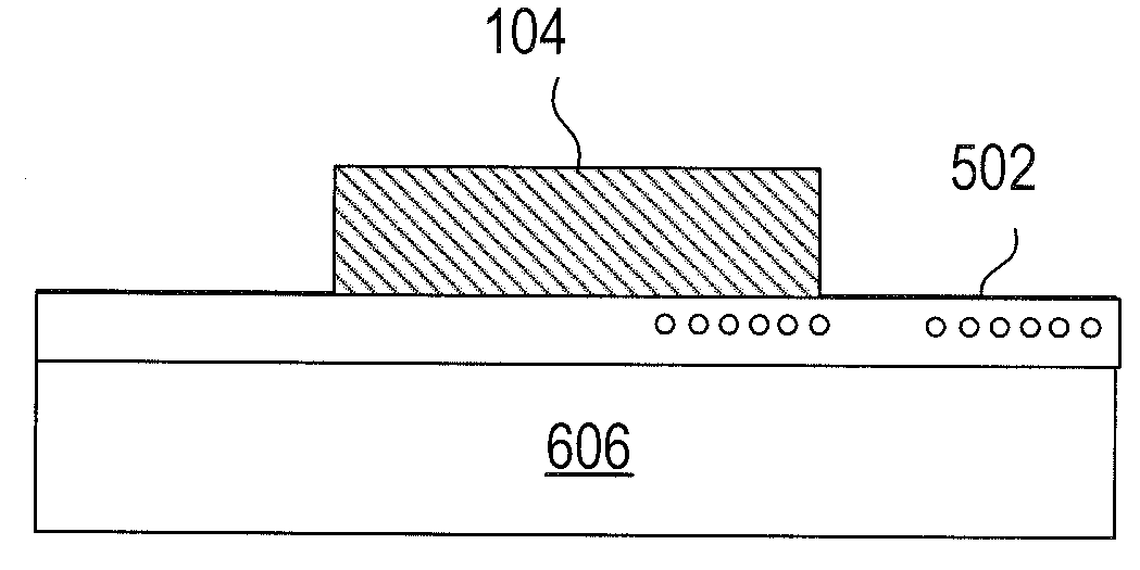
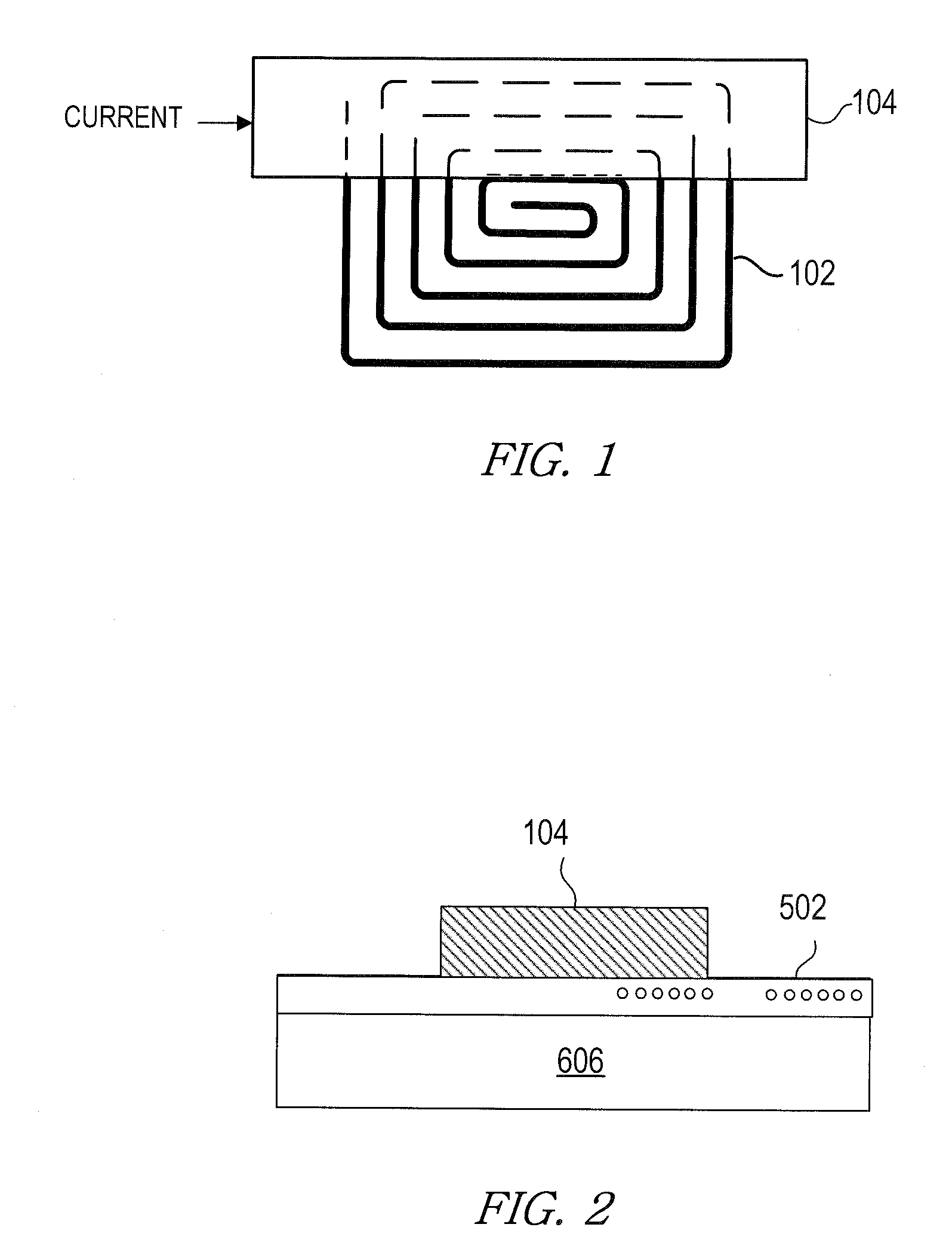
[0018]For example, FIG. 1 illustrates a coil or inductor 102 in close proximity with a large current carrying conductor (or slug) 104, such that the coil 102 and conductor 104 act as coupled inductors. The coupled inductors, along with on-chip electronics, which will be discussed herein below, allow for the creatio...


PUM


Abstract

In order to extend the measurement range of a current sensor, a current divider is formed by a first conductor formed in a current sensor that is mounted on a printed circuit board and a second conductor on the printed circuit board that electrically shorts at least one input terminal of the current sensor to at least one output terminal of the current sensor. The input terminal of the current sensor supplies the current to be measured to the first conductor and the output terminal supplies the measured current back to the printed circuit board.

Description

BACKGROUND[0001]1. Field of the Invention[0002]This invention relates to current sensors and more particularly to extending the current measurement range of current sensors.[0003]2. Description of the Related Art[0004]Various implementations of current sensors are used to measure high amperage AC current. For example, high amperage current may be measured using Rogowski coils surrounding the high amperage conductor. However, such approaches are not feasible in such applications where high amperage current, e.g., on the order of 100A, is carried on traces on a printed circuit board. Accordingly, improved techniques for measuring high amperage current are desirable.SUMMARY[0005]Accordingly, in one embodiment, an apparatus is provided that includes a printed circuit board and a current sensor coupled to the printed circuit board, the current sensor including a first conductor portion to carry a first current to be measured by the current sensor. The apparatus includes a second conducto...

Claims


Application Information

Patent Timeline
Patent Type & Authority Applications(United States)
IPC IPC(8): G01R19/00
CPCG01R15/181G01R1/203
Inventor ETTER, BRETT E.ALFANO, DONALD E.DUPUIS, TIMOTHY J.COFFEY, DONALD K.
Owner SILICON LAB INC
Why Eureka
Try Eureka