
Light-Emitting Diode Module with Heat Dissipating Structure

Inactive Publication Date: 2009-11-19
LIAO YUN CHANG
View PDF14 Cites 7 Cited by
  • Summary
  • Abstract
  • Description
  • Claims
  • Application Information

AI Technical Summary

Benefits of technology

[0020]All figures are drawn for ease of explanation of the basic teachings of the present invention only; the extensions of the figures with respect to number, position, relationship, and dimensions of the parts to form the preferred embodiment will be explained or will be within the skill of the art after the following teachings of the present invention have been read and understood. Further, the exact dimensions and dimensional proportions to conform to specific force, weight, strength, and similar requirements will likewise be within the

Problems solved by technology

However, directly assembling of the heat sink to the circuit board or substrate is not easy and could damage the LEDs during assembly.
However, the assembly of the heat generating electric part and the heat conductive block is complicated.
Further, the heat pipe is not in direct, thermal contact with the heat generating electric part, resulting in unsatisfactory heat dissipation effect.

Method used


Image

  • Light-Emitting Diode Module with Heat Dissipating Structure
  • Light-Emitting Diode Module with Heat Dissipating Structure
  • Light-Emitting Diode Module with Heat Dissipating Structure

Examples


Embodiment Construction

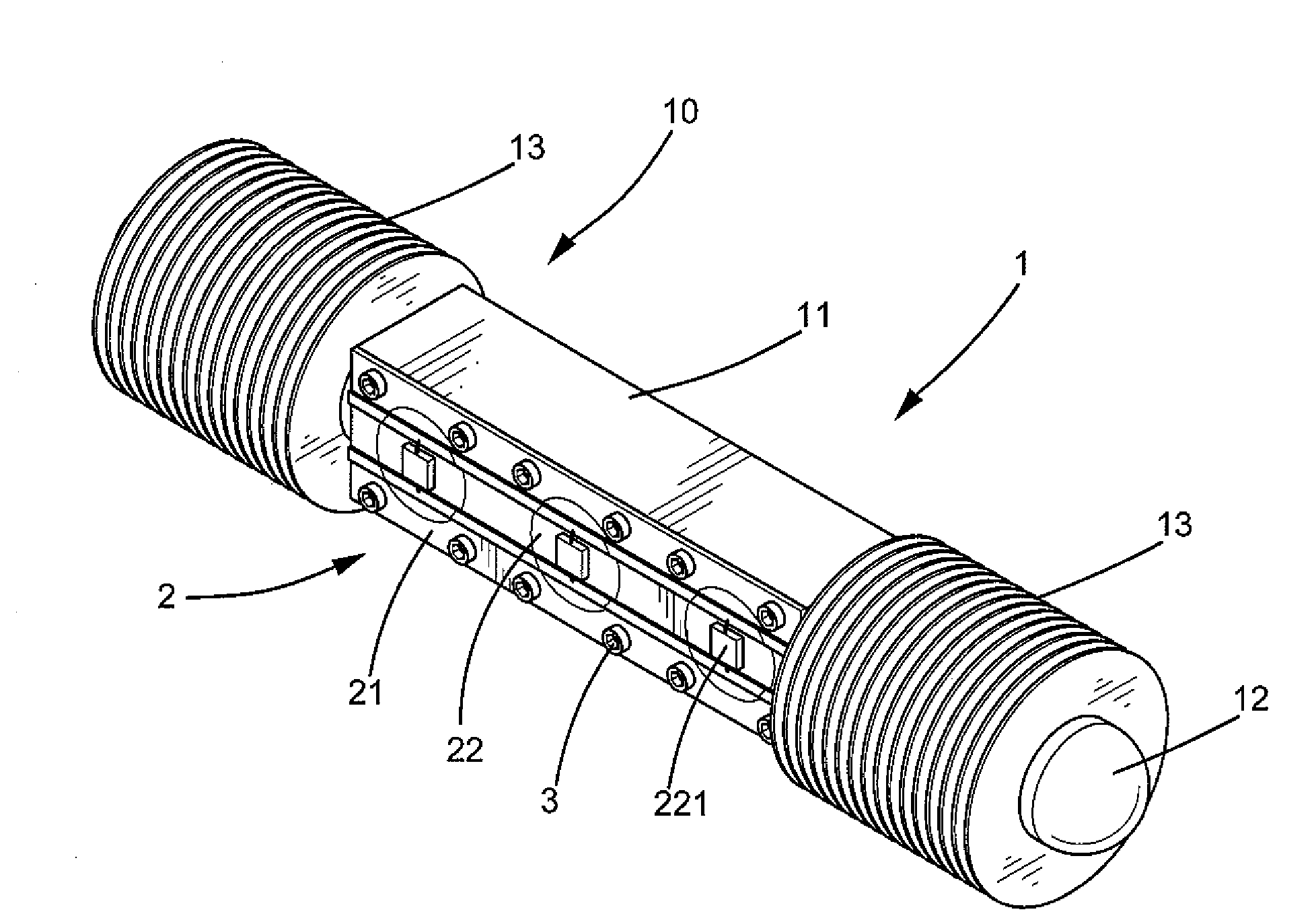
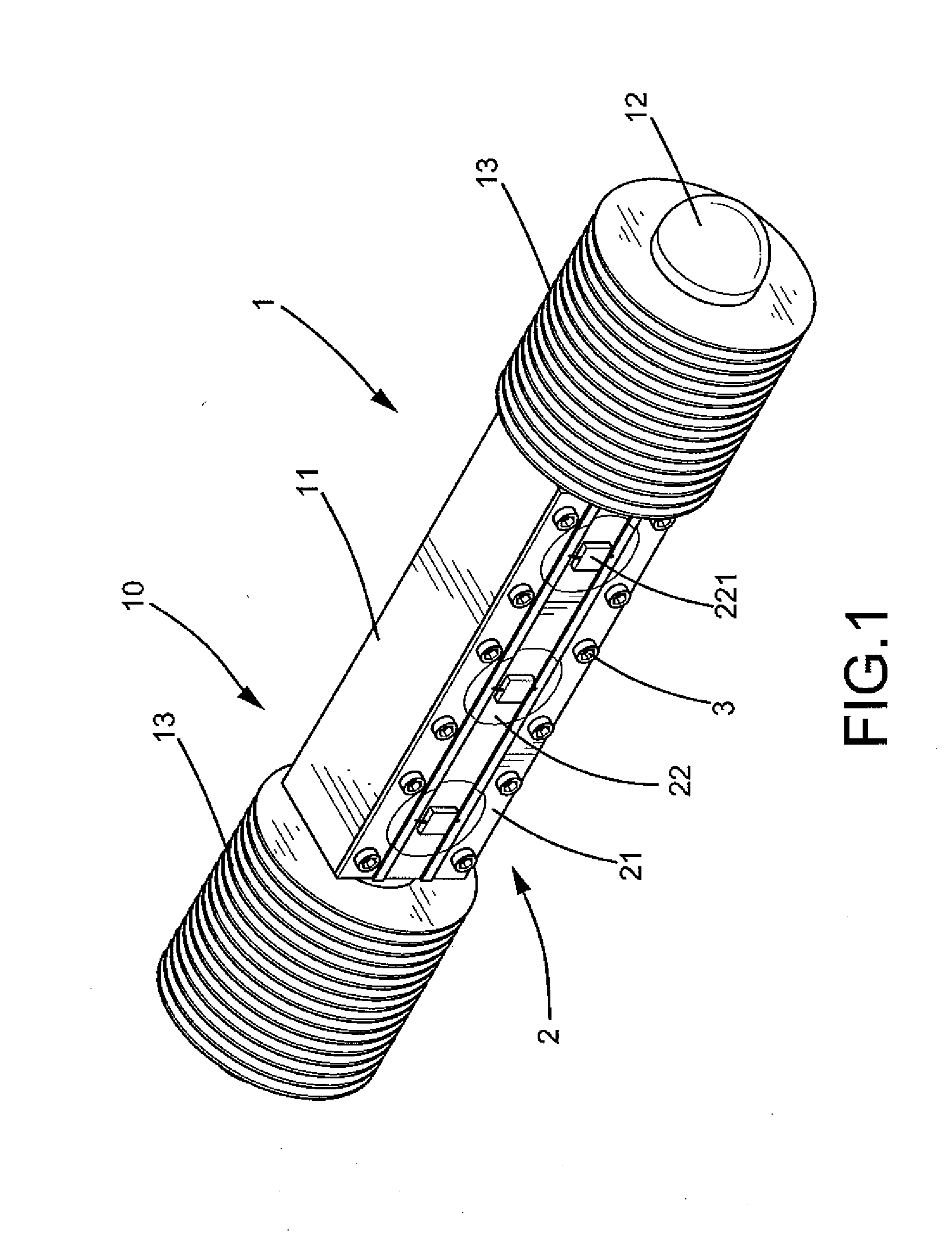
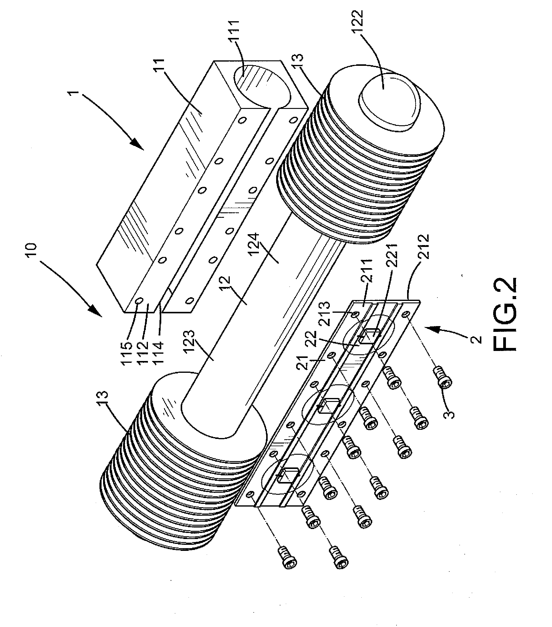
[0022]A light-emitting diode module with a heat dissipating structure of an embodiment according to the preferred teachings of the present invention is shown in FIGS. 1-4 of the drawings and generally designated 10. According to the preferred form shown, light-emitting diode module 10 includes a light-emitting diode (LED) light source assembly 2 including a metal substrate 21 having a first face 211 and a second face 212 opposite to first face 211, and a plurality of light-emitting diodes 22 as a light source. Each light-emitting diode 22 includes at least one LED die 221 mounted to first face 211 of metal substrate 21 and in direct, thermal contact with metal substrate 21. According to the most preferred form shown, metal substrate 21 has a thickness ranging from 0.5 to 1 mm and a plurality of through-holes 213 extending from first face 211 through second face 212.

[0023]According to the preferred form shown, light-emitting diode module 10 further includes a heat dissipating module ...


PUM


Abstract

A light-emitting diode module with a heat dissipating structure includes a metal substrate and a plurality of light-emitting diode dies mounted on a face of the metal substrate. A jacket has a coupling surface engaged with the other face of the metal substrate. A heat conduction pipe includes a portion received in a longitudinal hole of the jacket. The coupling surface of the jacket has an opening in communication with the longitudinal hole. A portion of an outer periphery of the portion of the heat conduction pipe is in direct, thermal contact with the other face of the metal substrate through the opening of the jacket to absorb heat generated by the light-emitting diode dies. A finned heat sink is mounted on another portion of the heat conduction pipe outside the jacket to dissipate heat transferred to the heat conduction pipe into the environment.

Description

BACKGROUND OF THE INVENTION[0001]The present invention relates to a light-emitting diode module, and more particularly, to a light-emitting diode module with a heat dissipating structure.[0002]Light-emitting diode modules including packaged light-emitting diodes (LEDs) are widely used as light sources in a variety of signs and image displays. LED dies generate heat during operation, which heat must be removed to keep high illumination efficiency. To this end, heat dissipating devices are provided to dissipate heat generated inside the light sources to the surrounding environment. Conventional heat dissipating devices for LED light sources generally include a heat sink connected to a circuit board or a substrate on which LEDs are disposed. However, directly assembling of the heat sink to the circuit board or substrate is not easy and could damage the LEDs during assembly.[0003]U.S. Pat. No. 4,204,246 disclosed a cooling assembly including a heat generating electric part, a heat condu...

Claims


Application Information

Patent Timeline
IPC IPC(8): F21V29/00
CPCF21K9/00F21V29/83F21W2131/103F21Y2101/02F21Y2111/005F21V19/0055F21S8/086F21Y2103/003F21V29/006F21V29/506F21V29/507F21V29/713F21V29/717F21V29/763F21V29/004F21Y2103/10F21Y2115/10F21Y2107/30F21V29/51
Inventor LIAO, YUN-CHANG
Owner LIAO YUN CHANG
Learn More