Wireless transmitting apparatus, wireless receiving apparatus, wireless transmission method, wireless reception method, wireless communication systems, and wireless communication method

Active Publication Date: 2009-11-19
NIPPON TELEGRAPH & TELEPHONE CORP
View PDF9 Cites 79 Cited by
  • Summary
  • Abstract
  • Description
  • Claims
  • Application Information

AI Technical Summary

Benefits of technology

[0065]The wireless transmitting apparatus and the wireless receiving apparatus can realize a frame configuration shown in FIG. 17 or 18. The pilot signals shown in FIG. 17 or FIG. 18 are arranged at a constant interval and synchronization data required for carrier recovery, symbol timing recovery, frame synchronization, and channel distortion compensation are contained as a common training signal. In comparison with the frame configuration used in the conventional wireless transmitting apparatus and wireless receiving apparatus shown in FIG. 28, it is not necessary to separately arrange data required for carrier recovery, symbol timing recovery, and frame synchronization in the frame. Therefore, the transmission efficiency (frame efficiency) can be increased even when the communication traffic of short packets is predominant.
[0066]Since carrier frequency estimation of the invention uses pilot signals, which are known signal sequence, arranged at equal intervals in a burst, highly precise carrier frequency synchronization performances can be obtained even with a short packet length and in regions of low CNR. In conventional wireless transmitting apparatuses and receiving apparatuses, code sequence data is embedded in adjacent symbols in the burst. Therefore, since a peak must be detected by making a comparison of cross-correlation values for a random signal sequence while deviating the frame position, the sequence length must have a certain degree of length. In contrast in the wireless receiving apparatus of the invention, frame synchronization is performed using the orthogonality of a plurality of synchronization code sequences generated by the pilot signal generating circuit. Also, a code sequence that is differentially encoded in pilot insertion internal units, instead of adjacent symbols, is used. Therefore in the invention, in the range of pilot overlap generated when a frame is deviated forwards or rearwards, the code patterns intersect and the correlation values are noticeably reduced, achieving highly precise frame detection even with a short synchronization code

Problems solved by technology

In carrier recovery used in sequential demodulation methods, a certain amount of burst length is needed to maintain pull-in precision, leading to a problem that carrier frequency synchronization performances deteriorate as the packet length is compressed.
However, in a block demodulation method in which a wireless burst is configured only by data symbols, when the packet length is extremely

Method used


Image

  • Wireless transmitting apparatus, wireless receiving apparatus, wireless transmission method, wireless reception method, wireless communication systems, and wireless communication method
  • Wireless transmitting apparatus, wireless receiving apparatus, wireless transmission method, wireless reception method, wireless communication systems, and wireless communication method
  • Wireless transmitting apparatus, wireless receiving apparatus, wireless transmission method, wireless reception method, wireless communication systems, and wireless communication method

Examples


Example

Example 1

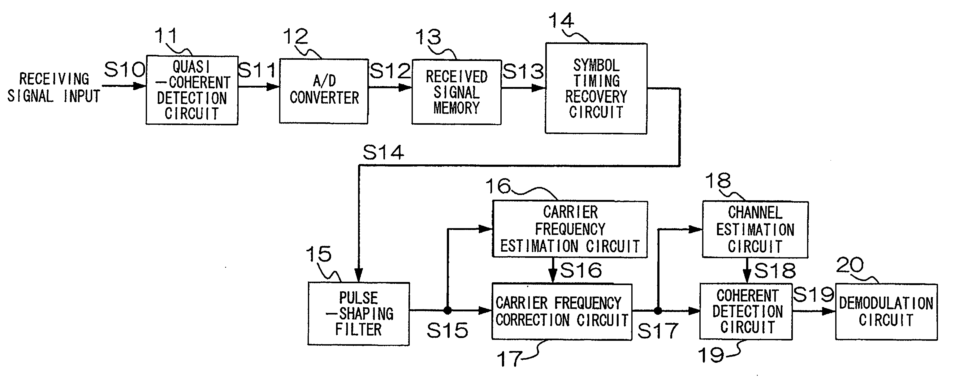
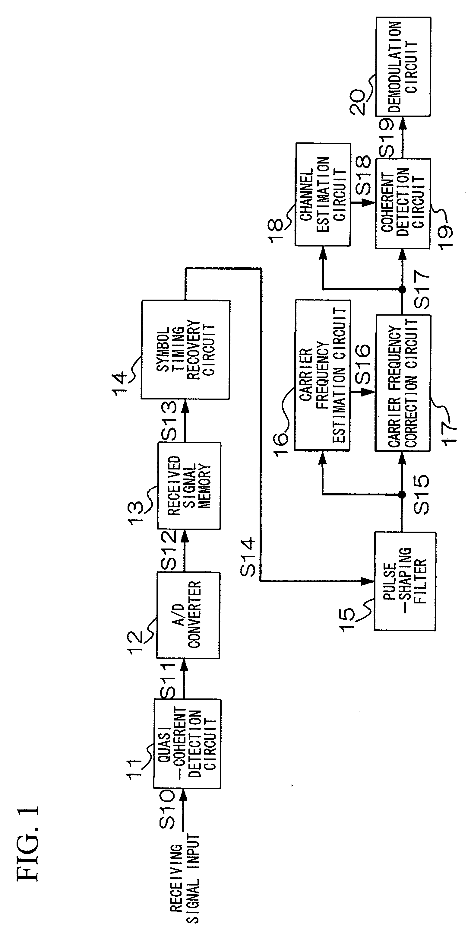
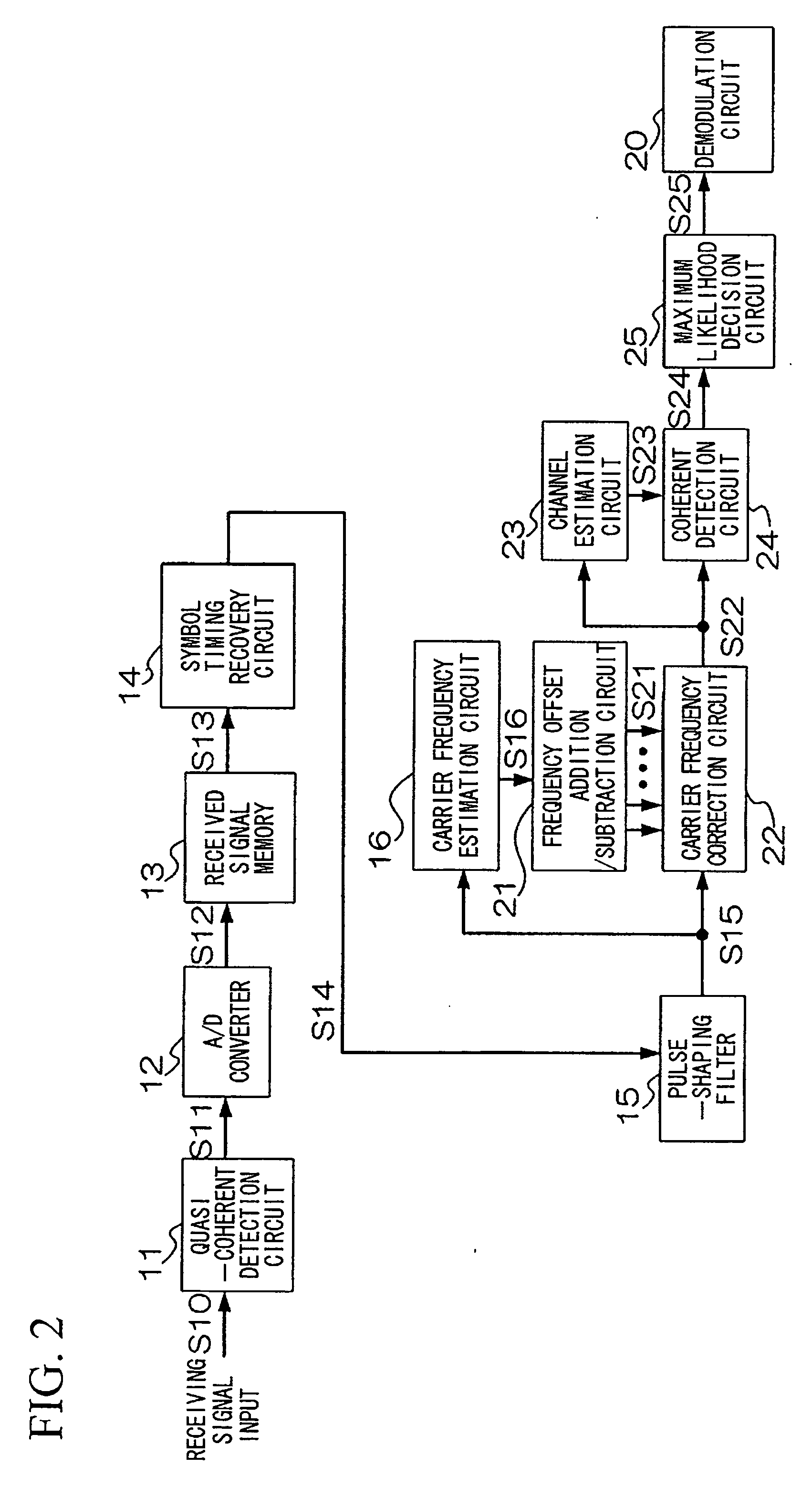
[0217]An example using the first and second embodiments of the invention shown in FIGS. 1 and 2 will be explained with reference to FIGS. 13 to 15. Cumulative probability distribution of residual carrier frequency estimation error and packet error rate characteristics of the wireless receiving apparatuses of FIG. 1 and FIG. 2 will be compared using computer simulations. FIG. 13 is a diagram of parameter comparison conditions in this example. While the wireless receiving apparatus of FIG. 1 uses a single estimated carrier frequency, the configuration of FIG. 2 uses three estimated carrier frequencies in consideration of the affects of frequency slips. QPSK modulation is used, and it is assumed that the apparatus has a diversity configuration including two receiving antennas, and that the channel is a flat Rayleigh fading channel. The burst length is 148 symbols, the data packet length is 128 symbols (16 bytes), and five pilot signals are provided, each having a length of fou...

Example

Example 2

[0249]An example using the embodiments of the wireless receiving apparatus and the wireless transmitting apparatus of the invention shown in FIGS. 16, 19, 21, and 22 will be explained with reference to FIGS. 24 and 25. Here, a comparison of packet error rate characteristics is made using computer simulation. FIG. 24 illustrates parameter comparison conditions in this example. It is here assumed that modulation is by QPSK, the channel is a single-path Rayleigh fading channel, and that a short packet with a data packet length of 16 bytes (128 symbols) is used. There are five pilot signals, each having a length of four symbols. A comparison is made of packet error rates of an apparatus without receive diversity and one with two-branch receive diversity with maximal ratio combining in a case where synchronization is made ideal.

[0250]FIG. 25 is a diagram of packet error rate characteristics against carrier-to-noise power ratio in the second example. In this example of the invent...

Example

Example 3

[0258]FIG. 30 is a diagram of an example of a channel linear interpolation estimation method in a third example of the invention.

[0259]FIG. 31 is a first diagram of an example of a channel averaging interpolation estimation method in the third example of the invention.

[0260]FIG. 32 is a second diagram of an example of a channel linear interpolation estimation method in the third example of the invention.

[0261]FIG. 33 is a diagram of parameter comparison conditions in the third example of the invention.

[0262]FIG. 34 is a diagram of performances in a third example of the invention.

[0263]An example using the wireless transmitting apparatus and the wireless receiving apparatus of the invention shown in FIGS. 16, 19, 21, 22, and 29 will be explained with reference to FIGS. 30, 31, 32, 33, and 34. Packet error rate (PER) characteristics for different channel interpolation methods will be compared using computer simulations.

[0264]As shown in FIG. 30, an interpolation method in the...


PUM


Abstract

A wireless transmitting apparatus inserts a training signal into a transmission burst at fixed symbol intervals as a pilot signal, a wireless receiving apparatus performs AD conversion of a received burst signal, performs symbol timing recovery, performs frame position detection and pilot signal extraction from the received burst signal for which symbol timing was established, performs frame synchronization, and performs a carrier frequency estimation using pilot signal. A carrier frequency estimation is also performed with respect to a received burst signal for which frame synchronization was established, and channel distortion is estimated and output based on a frequency-corrected received burst signal. Channel distortion estimation is then performed with respect to a frequency-corrected received burst signal, and a data symbol sequence of the channel-compensated received burst signal is converted to a received data bit stream.

Description

TECHNICAL FIELD[0001]The present invention relates to a wireless transmitting apparatus, a wireless transmission method, and a wireless-communication system in a digital wireless communication system, that is, a signal transmission system utilizing digital wireless communication technology. The invention particularly relates to a wireless transmitting apparatus, a wireless receiving apparatus, a wireless transmission method, a wireless reception method, a wireless communication system, and a wireless communication method, which utilize block demodulation. In accordance with the block demodulation, burst signals that have been received by a wireless receiving apparatus are block-stored in a storage unit or in a storing process and the block-stored signals are then applied to a digital signal processing, thereby performing burst synchronization and demodulation (symbol decision).[0002]Priority is claimed on Japan Patent Application No. 2005-257539, filed Sep. 6, 2005, Japan Patent App...

Claims


Application Information

Patent Timeline
IPC IPC(8): H04B7/00H04L27/00
CPCH04L25/0226H04L25/0232H04L27/3836H04L2027/0065H04L2027/0093H04L27/2695H04L27/2656H04L27/2657H04L27/2675H04L27/2692H04L27/261Y02D30/70H04L27/18
Inventor FUJITA, TAKAFUMIUCHIDA, DAISEIFUJINO, YOSUKEKAGAMI, OSAMUUMEHIRA, MASAHIRO
Owner NIPPON TELEGRAPH & TELEPHONE CORP
Why Eureka
Try Eureka