
Robot, robot hand, and method of controlling robot hand

a robot and hand technology, applied in the field of robots, can solve problems such as the inability to measure transparent objects, and achieve the effect of safe gripping the objects

Active Publication Date: 2009-11-19
SAMSUNG ELECTRONICS CO LTD
View PDF8 Cites 86 Cited by
  • Summary
  • Abstract
  • Description
  • Claims
  • Application Information

AI Technical Summary

Benefits of technology

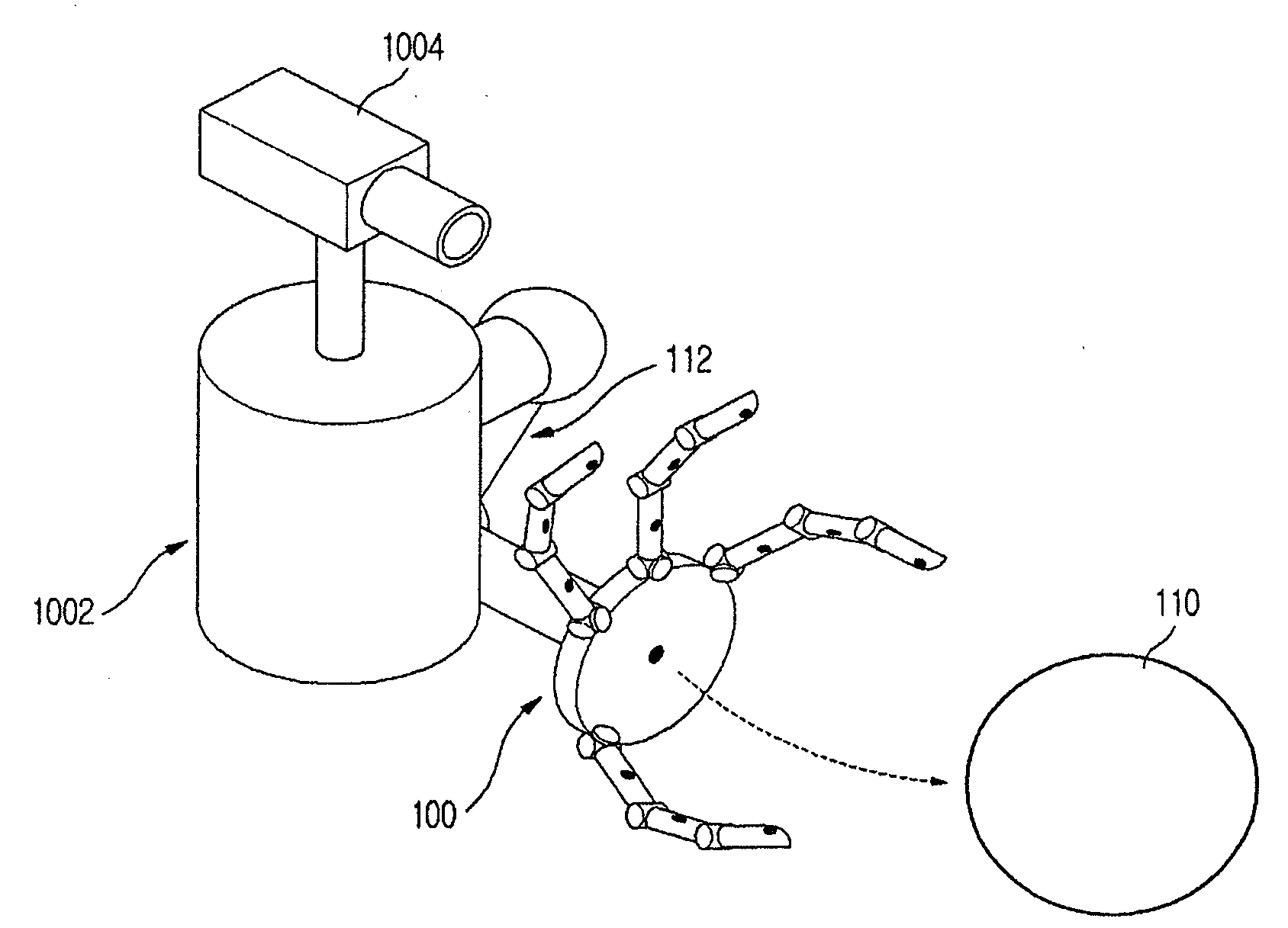
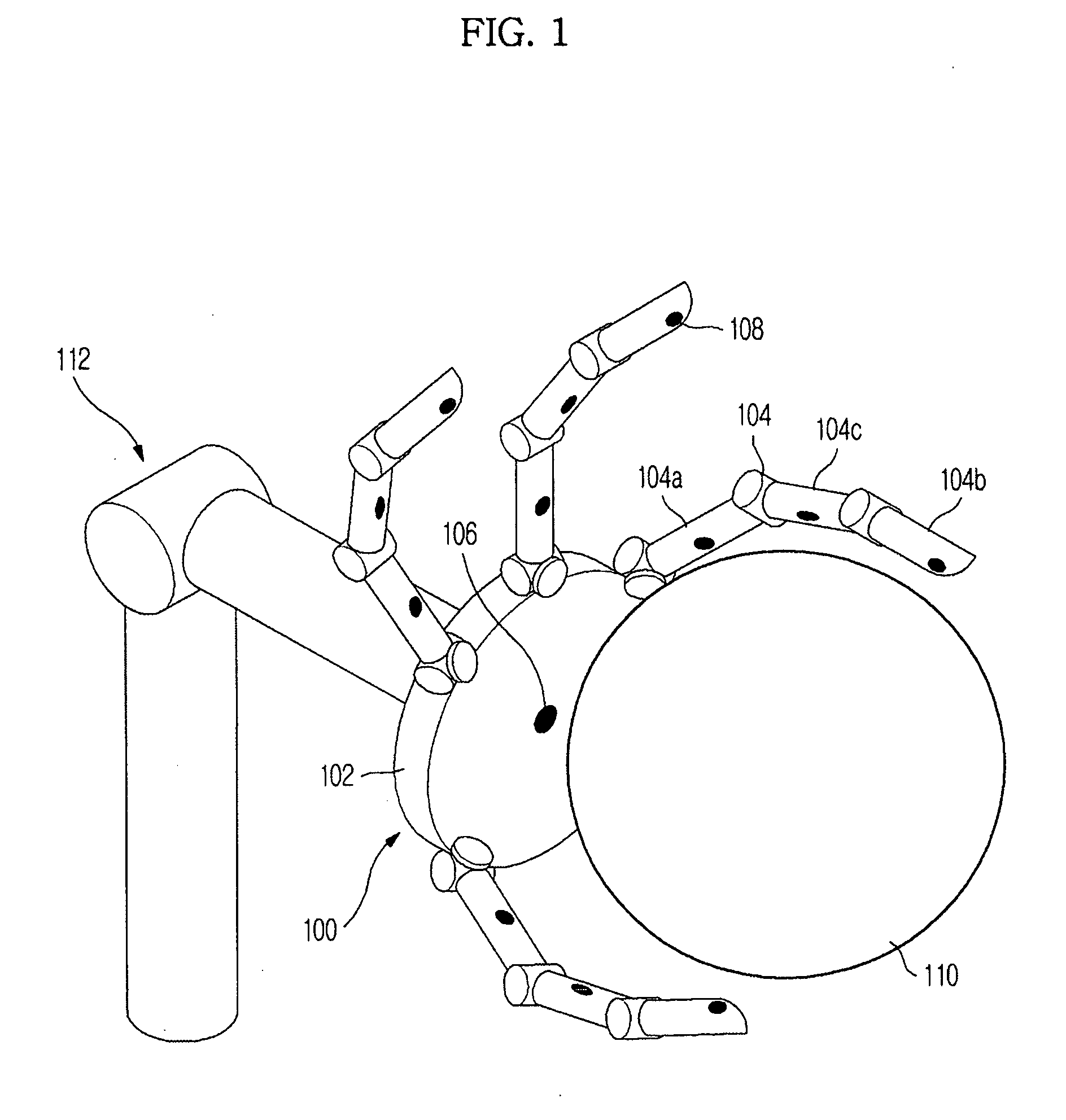
[0011]Accordingly, it is an aspect of the present invention to provide a robot, a robot hand, and a method of controlling the robot hand, in which the robot hand rapidly and correctly approaches an object to be gripped and safely grips the object regardless of the shape and material of the object.
[0015]The at least one first distance sensor and the at least one second distance sensor may be sequentially operated with a time difference, when the distances between the at least one first and second distance sensors and the object are measured, to prevent interference between the at least one first and second distance sensors.
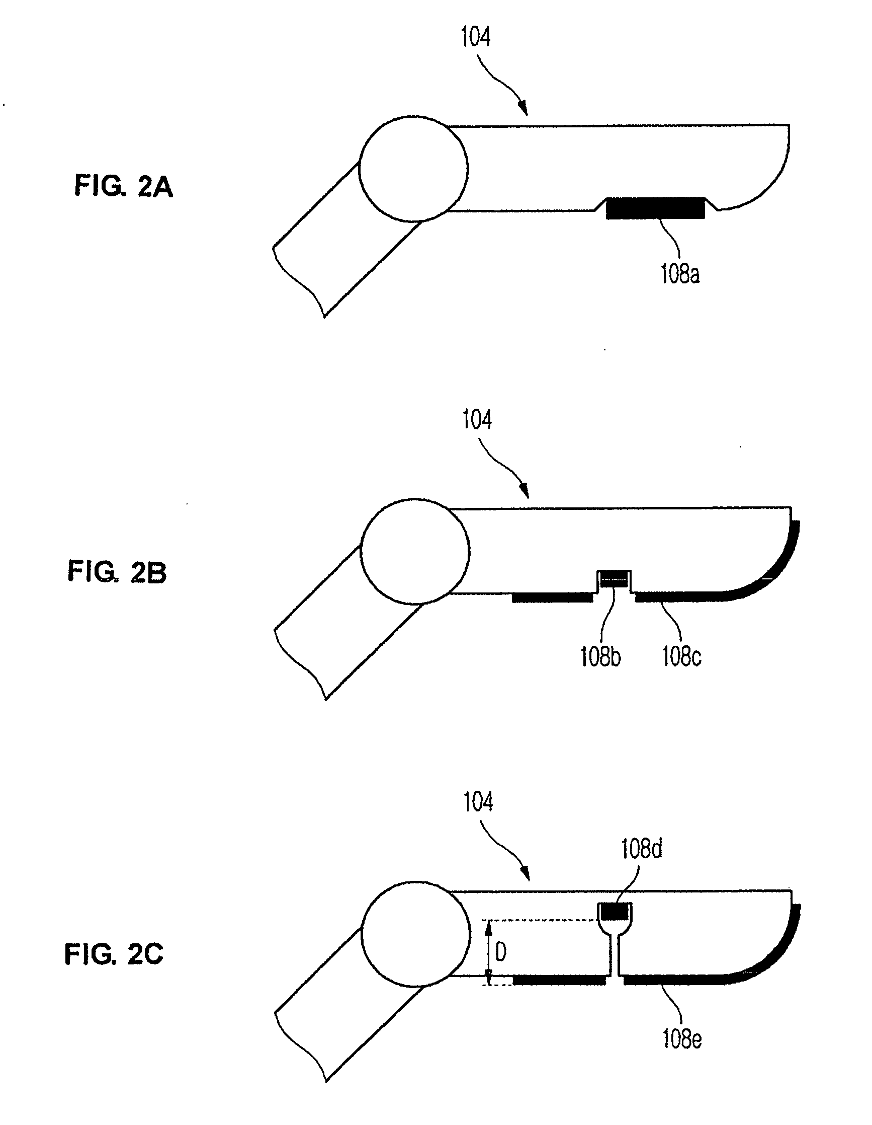
[0016]The foregoing and / or other aspects of the present invention are achieved by providing a method of controlling a robot hand, which has a palm, and a plurality of fingers, each having a plurality of segments, connected to the palm, including causing tip segments of the plurality of fingers to approach an object concurrently at a uniform distance and speed using at least one first distance sensor installed on the palm and at least one second distance sensor installed on the tip segments of the plurality of fingers; and causing the tip segments of the plurality of fingers to come into contact with the object to grip the object.
[0018]The method may further include, prior to the approach of the tip segments of the plurality of fingers to the object, generating a gripping route; and causing the robot hand to approach the object along the gripping route.
[0020]The at least one first distance sensor and the at least one second distance sensor may be sequentially operated with a time difference, when the distances between the at least one first and second distance sensors and the object are measured, to prevent interference between the at least one first and second distance sensors.
[0022]The shape of the object may be determined from the data of the measured distances based on the present position and posture of the robot hand. The posture of the robot hand may be defined by the relative directions and angles of the plurality of fingers to the palm. The plurality of distance sensors may be sequentially operated with a time difference, when the distances between the plurality of distance sensors and the object are measured, to prevent interference between the plurality of distance sensors.

Problems solved by technology

Robots conduct operations in dangerous working environments, repetitive operations, and operations requiring a large force.
Further, the conventional technique measures the distance with the object through a beam reception angle while moving the gripper itself, thus requiring an additional process to move the gripper to measure the distance with the object.
Moreover, the conventional technique uses light, thus being incapable of measuring a transparent object.

Method used


Image

  • Robot, robot hand, and method of controlling robot hand
  • Robot, robot hand, and method of controlling robot hand
  • Robot, robot hand, and method of controlling robot hand

Examples


second embodiment

[0062]FIG. 4 is a flow chart illustrating a method of controlling a robot hand in accordance with the present invention, and FIGS. 5A to 5E are views illustrating operating states of the robot hand controlled by the method of FIG. 4. In FIG. 4 and FIGS. 5A to 5E, an operation given to the robot hand 100 is to grip the object 110. As shown in FIG. 4 and FIGS. 5A to 5E, a gripping route, i.e., a moving route of the robot hand 100 for approaching the object 110, is generated (402). The gripping route is generated based on the relative position data of the object 110 against the robot hand 100, which are provided in advance. The arm 112 is controlled such that the robot hand 100 approaches the object 110 along the gripping route (404).

[0063]When the robot hand 100 approaches the object 110, the arm 112 and the robot hand 100 are controlled such that the distances between all the distance sensors 108 of the robot hand 100 and the object 110 are equal (406). Although the robot hand 100 ap...

third embodiment

[0067]FIG. 6 is a flow chart illustrating a method of controlling a robot hand in accordance with the present invention, and FIGS. 7A to 7D are views illustrating operating states of the robot hand controlled by the method of FIG. 6. In FIG. 6 and FIGS. 7A to 7D, an operation given to the robot hand 100 is to grip the object 110. As shown in FIG. 6 and FIGS. 7A to 7D, a gripping route, i.e., a moving route of the robot hand 100 approaching the object 110, is generated (602). The gripping route is generated based on the relative position data of the object 110 against the robot hand 100, which are provided in advance. The arm 112 is controlled such that the robot hand 100 approaches the object 110 along the gripping route (604).

[0068]When the robot hand 100 approaches the object 110, the arm 112 and the robot hand 100 are controlled such that the distances between all the distance sensors 108 of the robot hand 100 and the object 110 are equal (606). Although the robot hand 100 approa...

fourth embodiment

[0071]FIG. 8 is a flow chart illustrating a method of controlling a robot hand in accordance with the present invention, and FIGS. 9A to 9D are views illustrating operating states of the robot hand controlled by the method of FIG. 8. In FIG. 8 and FIGS. 9A to 9D, an operation given to the robot hand 100 is to grip the object 110 having a much smaller size than that of the robot hand 100. As shown in FIGS. 9A to 9D, the object 110 has a quite small size, and thus can be sufficiently gripped by only the tip segments 108b of the plurality of fingers 104 without using the whole robot hand 100. As the occasion demands, the object 110 can be gripped by only the tip segments 108b of two fingers 104. Thus, the distances between the plurality of fingers 104 and the object 110 are measured by only the distance sensors 108 installed on the tip segments 104b of the plurality of the fingers 104. As shown in FIG. 8 and FIGS. 9A to 9D, a gripping route, i.e., a moving route of the robot hand 100 f...


PUM


Abstract

Disclosed are a robot, a robot hand, and a method of controlling the robot hand, in which the robot hand rapidly and correctly approaches an object to be gripped and safely grips the object regardless of the shape and material of the object. The method of controlling a robot hand, which has a palm, and a plurality of fingers, each having a plurality of segments, connected to the palm, includes causing the palm to approach an object using at least one first distance sensor installed on the palm; causing the plurality of fingers to approach the object using at least one second distance sensor installed on the plurality of fingers; and causing the palm and the plurality of fingers to come into contact the object to grip the object.

Description

CROSS-REFERENCE TO RELATED APPLICATIONS[0001]This application claims the benefit of Korean Patent Application No. 2008-0043773, filed May 13, 2008, in the Korean Intellectual Property Office, the disclosure of which is incorporated herein by reference.BACKGROUND[0002]1. Field[0003]The present invention relates to a robot, and more particularly, to a robot hand having a plurality of fingers and a method of controlling the same.[0004]2. Description of the Related Art[0005]Robots conduct operations in dangerous working environments, repetitive operations, and operations requiring a large force. Recently, robots are used in various fields of medical, military, aerospace, agricultural, and housekeeping industries as well as at industrial sites.[0006]Robots at industrial sites are widely used in various operations including welding, assembling, coating, testing, and transferring. In a robot used in a transferring operation, it is important to safely and correctly grip and transfer an obje...

Claims


Application Information

Patent Timeline
Patent Type & Authority Applications(United States)
IPC IPC(8): B25J15/08B25J15/10B25J19/04B25J13/08B25J9/00
CPCB25J9/1612B25J15/0009B25J13/086B25J13/081B25J19/02
Inventor KIM, YONG JAELEE, JA WOOPARK, KANG MIN
Owner SAMSUNG ELECTRONICS CO LTD
Learn More