
Control handle for a vessel and a vessel including such a control handle

a control handle and control handle technology, which is applied in the direction of mechanical control devices, instruments, vessel construction, etc., can solve the problems of increasing reducing the risk of hand injury to the driver, so as to reduce the risk of hand injury, increase the driver's control of the vessel, and improve the effect of maneuvering safety

Inactive Publication Date: 2009-07-23
ULLMAN JOHAN
View PDF6 Cites 0 Cited by
  • Summary
  • Abstract
  • Description
  • Claims
  • Application Information

AI Technical Summary

Benefits of technology

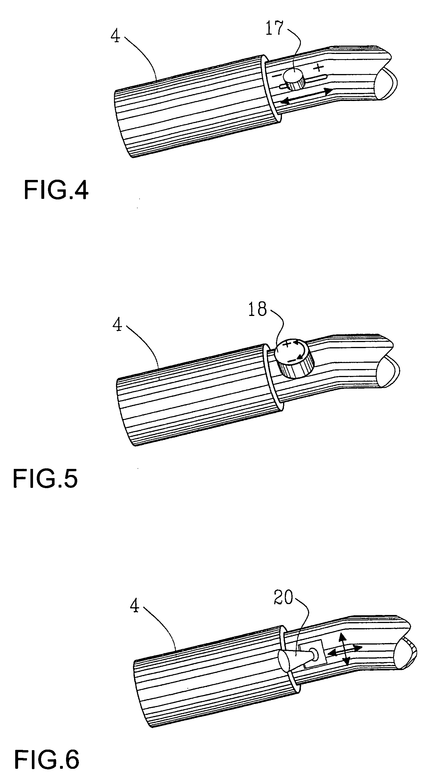
[0008]Said object is achieved with a control handle according to the characterizing portion of claim 1. By providing a control handle comprising a handle bar with two handles, where at least one additional control is provided at one of the handles, which control is accessibly arranged for adjustment of a desired position with a thumb or forefinger of the driver while keeping the rest of the fingers in a closed grip around the handle, there is provided a possibility of adjusting at least one additional function at the vessel, such as for example adjustment of the trimming tab angle, the propeller banking angle, distribution of propulsion force between a set of motors or selection of forward or backward propulsion, which function is necessarily adjusted under operation. In this way the driver does not need to neither move the hands from the handle bar nor loosen the grip of the handle bar during operation, which increases the driver's control of the vessel and decreases the risk of hand injury to the driver.
[0009]In a preferred embodiment, one or several additional controls are arranged on the thumb side of and in immediate vicinity of one of said handles. By such a placement, the driver can get access to the control handle or the control handles without loosen the grip around the handle bar and with a maintained grip around the handle bar. The driver only needs to open the forefinger or alternatively move the thumb to be able to effect the control handle. Thus, the rest of the fingers can be held clenched around the handle, which gives a safe grip for the driver.
[0010]In a preferred embodiment of the invention, a throttle control in the form of a throttle twist grip. By using a throttle twist grip, a control device is provided for a throttle control where the driver with a closed grip around the handle can adjust the throttle, which results in good maneuvering safety.
[0011]In an additional preferred embodiment of the invention, additional controls are provided on surfaces which are substantially facing each other, whereby good accessibility of the controls are obtained without the driver needing to loose the grip of the handle.
[0012]By providing a vessel comprising at least a driving motor, ailerons or a trimming tabs for adjustment of the vessel's position during operation and a control handle for said vessel where said control handle comprises a handle bar, a first and a second handle supported by the handle bar with throttle control and control handles for ailerons or trimming tabs are accessibly arranged for adjustment of a desired position with a maintained, closed grip by middle finger, ring finger and little finger around the handle, a vessel is obtained where controls which are necessary to access during ride are arranged so that access is guaranteed where the driver does not need to move his hands from the handle bar or loosen the grip around the handle bar during operation, which increases the driver's control of the vessel and decreases the risk of hand injuries to the driver.

Problems solved by technology

In this way the driver does not need to neither move the hands from the handle bar nor loosen the grip of the handle bar during operation, which increases the driver's control of the vessel and decreases the risk of hand injury to the driver.

Method used


Image

  • Control handle for a vessel and a vessel including such a control handle
  • Control handle for a vessel and a vessel including such a control handle
  • Control handle for a vessel and a vessel including such a control handle

Examples


Embodiment Construction

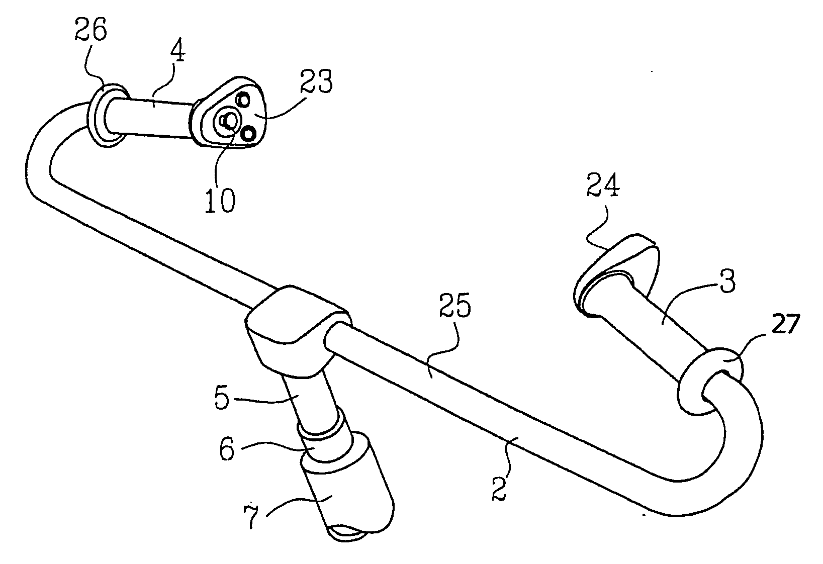
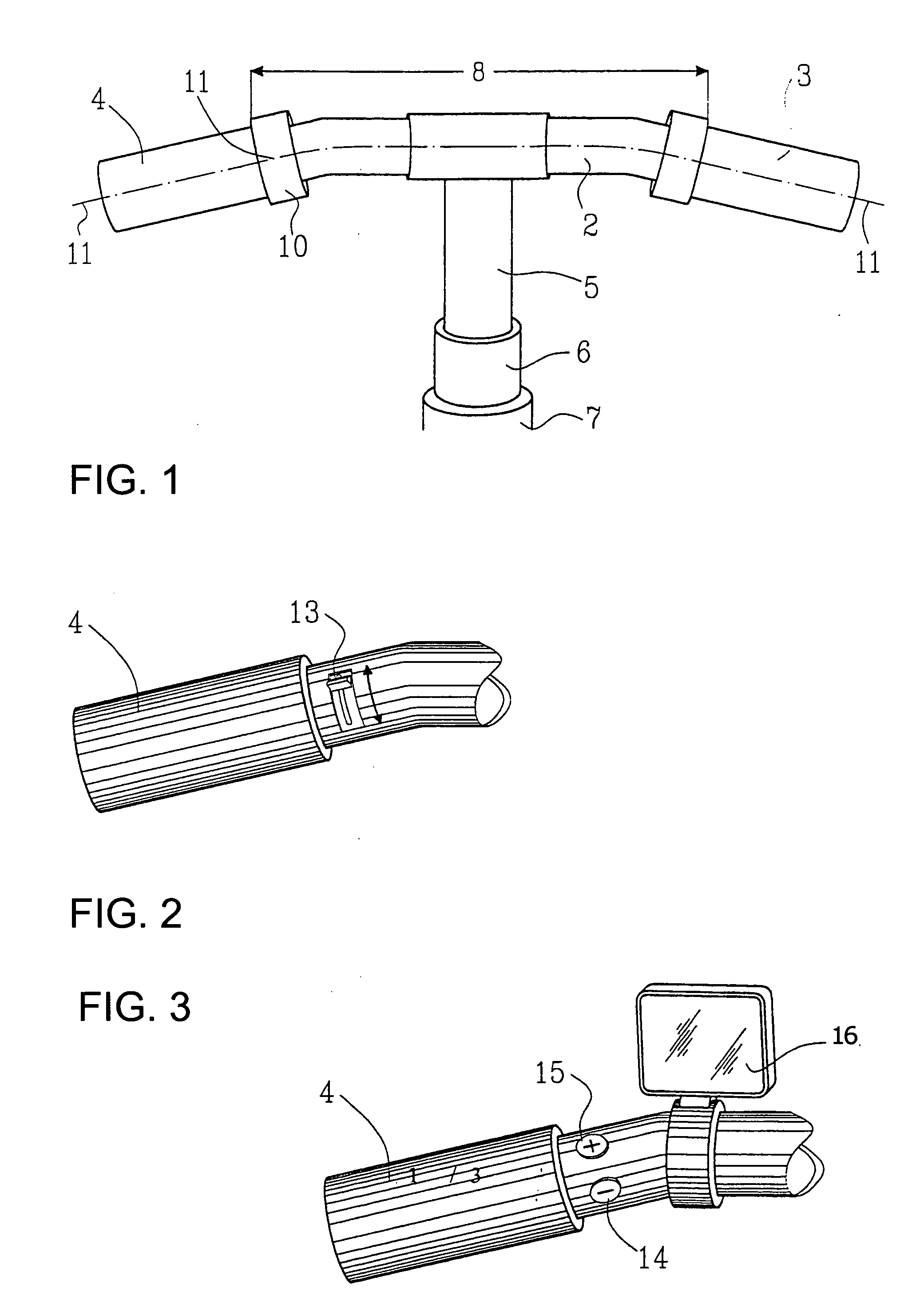
[0024]FIG. 1 shows a control handle 1 for a vessel comprising a handle bar 2, the handle bar being provided with a first handle 3 having a throttle twist grip and a second handle 4. The handle bar 2 is supported by a rotatably mounted steering axle 5, which is rotatably supported in a steering column 6 which is mounted to a support 7. The support is thereafter mounted in a known way to a not shown vessel. In a preferred embodiment of the invention the handle bar 2 comprises a centre portion 8 which extends substantially perpendicular to the steering axle 5. Two handles 3, 4 extend out from each side of the centre portion. Preferably, the handles 3, 4 are directed slightly backwards downwards in the vessel, which results in an ergonomic grip. In a preferred embodiment, the handles are inclined about 15° backwards towards the driver in relation to the centre portion of the handle bar.

[0025]Further, at one of said handles 3, 4 it is provided at least one additional control handle 10, w...


PUM


Abstract

A control handle for a vessel, the control handle having a handle bar, two handles, at least one throttle control arranged in connection with one or both handles, and an additional control. A vessel having a control handle for a vessel with a handle bar, two handles, at least one throttle control arranged in connection with one or both handles, and an additional control. The throttle control can be a twist grip. The additional control can be for adjustment of one or several of: shifting between forward or backward propulsion of the vessel, force distribution between motors provided on the vessel, adjustment of an angular position of trimming tabs of the vessel, adjustment of a banking angle of a propeller drive provided in the vessel, and adjustment of a position of a reversing scoop of a water jet.

Description

TECHNICAL FIELD[0001]The patent application concerns a control handle for a vessel and a vessel. Further, it concerns a vessel with water jet propulsion. Especially, it concerns a control handle and a vessel including a control handle, where the control handle comprises a handle bar.BACKGROUND OF THE INVENTION[0002]Today's motorboats are mostly controlled by a steering wheel. The rotation speed control for acceleration and retardation of the motorboat is usually made using one or two levers mounted on a support at a distance from the steering wheel. Shifting between forward and backward propulsion is usually controlled with an additional lever, which is usually arranged on said support.[0003]In some vessels, especially in so-called water scooters, the steering wheel has been replaced by a handle bar. The usage of a handle bar instead of a steering wheel leads to a number of advantages for the driver. A handle bar provides for better control of the boat as the proprioceptive signals ...

Claims


Application Information

Patent Timeline
Patent Type & Authority Applications(United States)
IPC IPC(8): B63H20/12G05G1/10B63B34/10B63H21/22
CPCB63B35/731Y10T74/20732B63H21/213B63B34/10
Inventor ULLMAN, JOHAN
Owner ULLMAN JOHAN
Learn More