
Wound dressing

a wound dressing and wound technology, applied in the field of wound dressings, can solve the problems of wound and surrounding skin not being observed once, dressing fragments having to be removed, and limited use of such dressings in sinus or cavity wounds, etc., and achieve the effect of reducing the problem

Active Publication Date: 2009-11-19
CONVATEC TECH INC
View PDF7 Cites 19 Cited by
  • Summary
  • Abstract
  • Description
  • Claims
  • Application Information

AI Technical Summary

Benefits of technology

[0007]The present invention seeks to provide improved wound dressings which mitigate the problems associated with ribbon dressings in cavity or sinus wounds.
[0008]We have now found that it is possible to improve the tensile strength of strip dressings in a dry or wet (gelled) state.
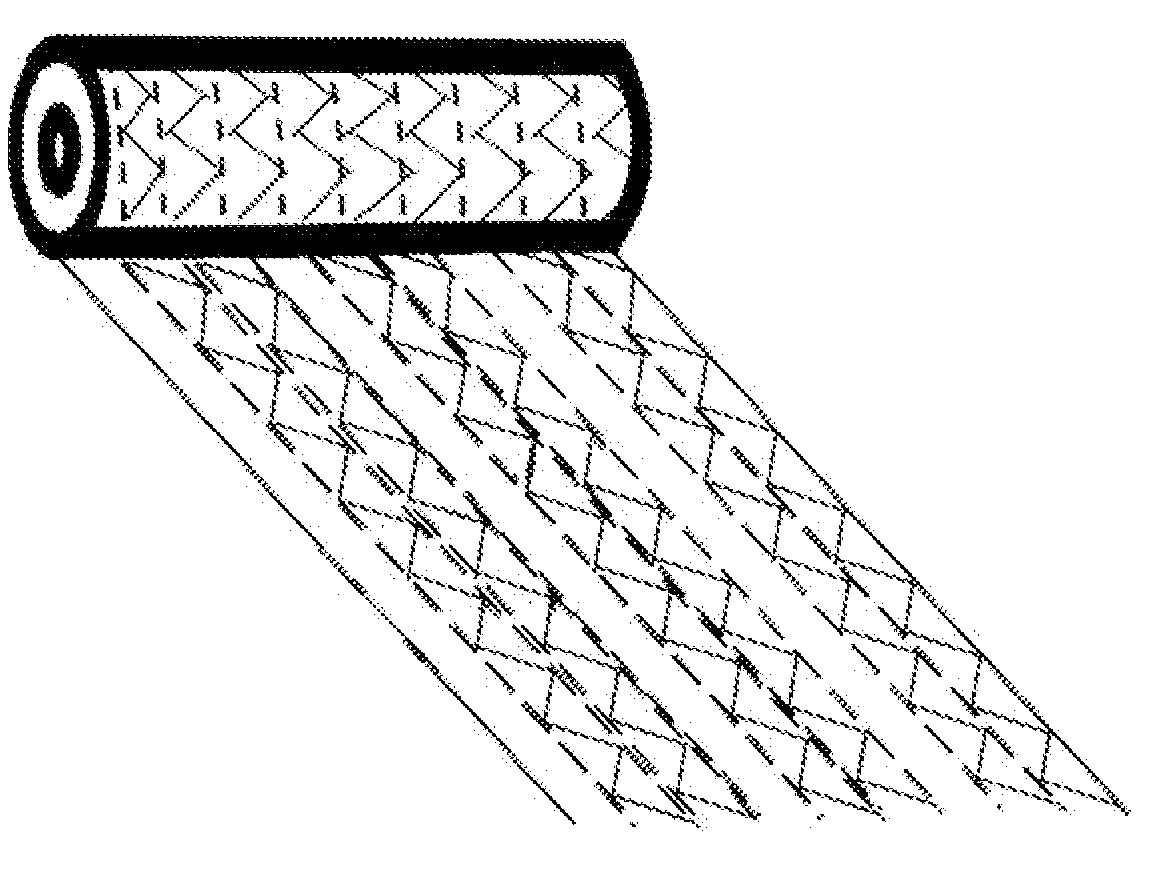
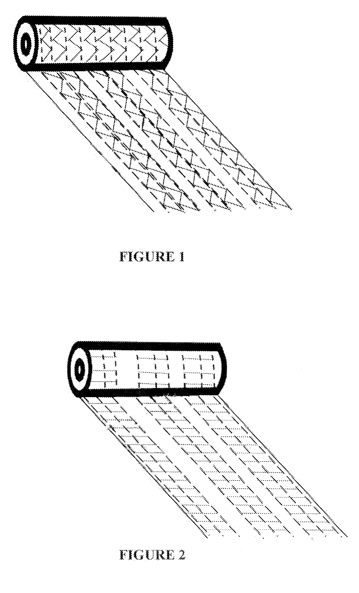
[0018]The dressing may be in the form of 0.5, 1, 2 or more meter lengths and be approximately 0.5 cm to 10 cm wide, preferably from 0.5 cm to 5 cm wide. The longitudinal lines of stitching may be from 1 mm to 10 mm apart and, preferably, from 2 mm to 5 mm apart. The lines of longitudinal stitching may be a lock stitch and may typically be crochet or chain stitch, but other stitch patterns may also be used. The rows of transverse stitching may be from 1 mm to 10 mm apart and, preferably, from 2 mm to 5 mm apart. The transverse lines of stitches may be a pattern stitch and may be crocheted or may be a basting stitch between two layers of superposed gel-forming fibers. Preferably, the lines of stitching are made in a thread such as Tencel. The transverse stitches serve to link adjacent longitudinal lines of stitches together to add strength to the dressing in a transverse direction. The transverse lines of stitches are preferably made in columns between pairs of adjacent longitudinal lines of stitches with stitch free gaps between the columns to allow a roll of stitched gelling fabric to be slit in the gaps. This allows strips to be formed without creating loose ends of transverse stitching at the edges of the strip.
[0020]Preferably, the dressing comprises at least two longitudinal lines of stitching joined by a transverse line of stitching that runs in a column between the longitudinal lines. This allows the dressing to be slit from a roll with minimal loose ends of thread. More preferably, the dressing comprises at least four longitudinal lines of stitching arranged as two or more pairs of lines where the longitudinal lines of stitching in each pair are joined by a transverse line of stitching in the form of a column. This arrangement allows the user to further cut the dressing in the stitch free gap between the pairs of longitudinal lines of stitching to create a narrower ribbon.
[0028]Preferably, the transverse stitching is made in columns joining the longitudinal lines of stitching so that stitch free gaps are created between the columns. In this way a ribbon can be slit from the roll in the gaps so that minimal loose ends occur at the edges of the strip which could otherwise be lost into the wound. Preferably, the columns of transverse stitches are secured so that there are no loose threads in the gaps between the columns and the edges of the ribbon or strip have no loose ends. Preferably, the columns of transverse stitches are a continuous line of stitching which zig-zags between the longitudinal lines of stitches. In this way the columns have stitch free gaps in the space between the columns which allow the roll to be slit into strips with no loose ends at their edges.
[0029]Preferably, the dressing has several pairs of lines of longitudinal stitching with the lines in each pair joined by transverse stitching in a castellated pattern to create stitch free gaps between adjacent pairs of joined longitudinal lines of stitches. This allows the dressing to be cut into thinner ribbons by the user.

Problems solved by technology

The usefulness of such dressings is limited in respect of sinus or cavity wounds due to difficulty in removing the dressing from such a wound.
This presents a problem when the dressing needs to be removed as removal generally is done by pulling the ribbon out of the wound from one end of the ribbon.
The loss of tensile strength means that the dressing fragments on removal and has to be removed in many pieces or by flushing.
There are, however, disadvantages in doing so.
The scrim also renders the dressing opaque which means that the wound and surrounding skin cannot be observed once the dressing is in situ.
However, when longitudinal stitching is applied to a thin strip it gives strength only in the stitching direction and restricts how the dressing can be removed.

Method used


Image

  • Wound dressing
  • Wound dressing

Examples


example 1

Dressing A

[0035]A wound dressing was made from a roll of gel-forming fibers as described for the dressing of FIG. 1. The roll had lines of longitudinal stitching spaced 5 mm apart. The column width was 2.5 cm. Ribbons were cut from each roll by slitting in a longitudinal direction at the gaps between the columns in the transverse stitching.

Dressing B

[0036]An alternative wound dressing was made by superposing two rolls of gel-forming fibers as described for Dressing A and stitching as described for Dressing A.

Dressing C

[0037]An alternative wound dressing was made by eliminating the transverse stitching of Dressing A.

Dressing D

[0038]Was formed from 100 gsm Aquacel® a nonwoven dressing made from fibers of carboxymethyl cellulose manufactured by ConvaTec Inc.

[0039]Test samples were cut from the stitched rolls to have the dimensions 25 mm wide by 100 mm long for the wet samples and 25 mm wide by 75 mm long for the dry samples. The tensile strength of the gelled and dry samples were measu...

example 2

[0044]Dressing A was used to pack a tracking wound. On removal from the wound the ribbon dressing was fully hydrated with wound fluid yet had maintained its structure. The dressing was easily removed from the wound in one piece.


PUM

PropertyMeasurementUnit
Lengthaaaaaaaaaa
Lengthaaaaaaaaaa
Widthaaaaaaaaaa

Abstract

A wound dressing comprising a layer in the form of a strip and comprising gel-forming fibers, the strip having longitudinal lines of stitches formed from a thread and transverse lines of stitches formed from a thread.

Description

[0001]This invention relates to a wound dressing, in particular, to ribbon or strip dressing of the type composed of gel-forming fibers in the form of a woven or nonwoven layer or layers. In particular, the invention relates to dressings comprising gel-forming fibers used in the treatment of sinus or cavity wounds or post-operative wounds.BACKGROUND OF THE INVENTION[0002]It is known to use carboxymethylated cellulosic materials in situations where a high degree of exudate absorption is required. For example, WO 93 / 12275 describes the production of various absorbent products capable of absorbing many times their own weight of water. This causes the carboxymethylated fibers to form a gel. WO 94 / 16746 and WO 00 / 01425 describe the use of carboxymethylated Lyocell materials in wound dressings where the advantages of gel formation in preventing adherence and, therefore, reducing wound damage and pain on removal are discussed.[0003]Known wound dressings comprising gel-forming fibers are es...

Claims


Application Information

Patent Timeline
IPC IPC(8): A61F13/00D05B1/00
CPCA61F13/00021A61F2013/00936A61F13/00995A61F13/20A61F13/36A61F2013/00225A61F2013/00229A61F2013/00238A61F2013/00523A61F2013/0054A61F2013/00548A61F2013/00714A61F2013/00748A61F2013/00753A61F13/00063A61F13/01021
Inventor LEE, BRYONY JAYNECOTTON, STEPHEN MICHAEL
Owner CONVATEC TECH INC
Learn More