Clutch control system

a technology of clutch control and control system, which is applied in the direction of clutches, mechanical devices, instruments, etc., can solve the problems of increasing the weight of the system as a whole, difficult to simply apply the technology of japanese patent laid, and complicated structure, so as to facilitate vehicle start and enhance the degree of freedom of the driver

a technology of clutch control and control system, which is applied in the direction of clutches, mechanical devices, instruments, etc., can solve the problems of increasing the weight of the system as a whole, difficult to simply apply the technology of japanese patent laid, and complicated structure, so as to facilitate vehicle start and enhance the degree of freedom of the driver

US20090287387A1Active Publication Date: 2009-11-19HONDA MOTOR CO LTD

Image

  • Clutch control system
  • Clutch control system
  • Clutch control system

Examples


Embodiment Construction

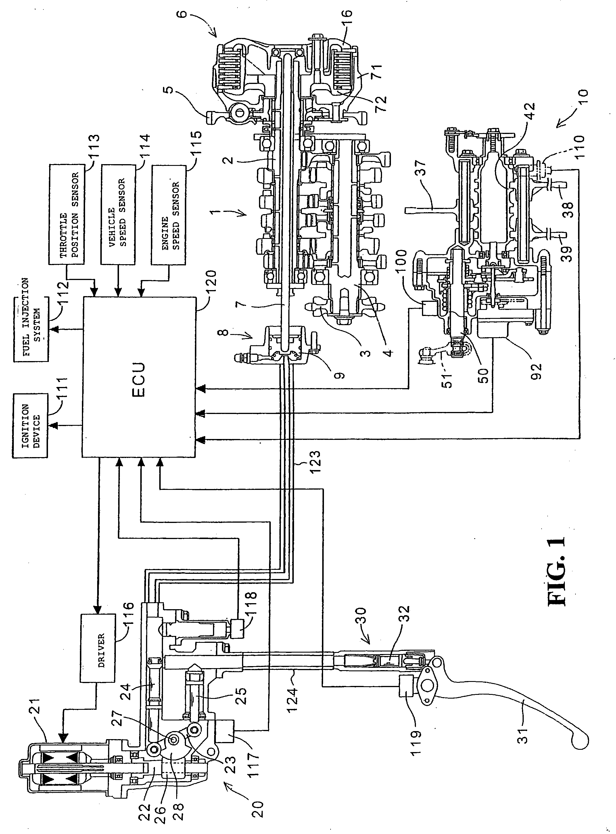
[0024]Now, a preferred embodiment of the present invention will be described in detail below, referring to the drawings. FIG. 1 is a block diagram showing the configuration of a clutch control system according to one embodiment of the present invention, together with the peripheral apparatuses. A transmission 1 applied to a motorcycle has 1st-speed to 6th-speed transmission gear pairs for transmitting a rotational driving force, between a main shaft 2 as an input shaft and a counter shaft 4 as an output shaft, both of which are rotatably borne on an engine case (not shown) while having axes parallel to each other. Incidentally, the transmission 1 of a normally meshed type, in which the transmission gear pairs are sequentially changed over by intermittently rotating a shift drum, has a configuration generally known as a sequential-type multi-gear-speed transmission for motorcycle. Therefore, detailed description of the transmission 1 is omitted.

[0025]A clutch 6 for switching the conn...


PUM


Abstract

When a predetermined time has passed without detection of engine stall and without detection of the neutral state and without detection of a vehicle starting operation, in a first control state in which a clutch is in a disengaged state, a clutch control system effects transition to a second control state in which transition to a third control state is permitted. When a vehicle starting operation is detected in the second control state B in which the clutch is in the disengaged state, a liquid pressure modulator is driven to effect transition to the third control state in which the clutch is put in the engaged state or a partially engaged state. When an engine stall or the neutral state is detected in the second control state, transition to the first control state A is effected.

Description

TECHNICAL FIELD[0001]The present invention relates to a clutch control system, particularly to a clutch control system which makes it possible to reduce the weight of the system as a whole while preventing a large driving force from acting on a transmission, by performing a predetermined vehicle start inhibition control.BACKGROUND OF THE INVENTION[0002]Automatic transmissions in which a clutch operation at the time of starting the vehicle and gear shift operations during running are performed automatically have been known.[0003]Japanese Patent Laid-open No. Sho 56-57525 discloses a configuration of an automatic transmission for shifting among D (drive: forward running), N (neutral) and R (reverse: reverse running) positions in the transmission by a shift lever operated by the rider (driver), wherein the gear shift from N to D or R is not effected even if the shift lever is operated in the condition where the engine speed or the throttle position (throttle opening) is not less than a...

Claims


Application Information

Patent Timeline
19 Nov 2009
Publication
US20090287387A1
IPC
G06F17/00; B60W10/02
CPC
F16D2500/10412; Y10T477/638; F16D2500/1117; F16D2500/3069; F16D2500/30808; F16D2500/3144; F16D2500/50224; F16D2500/70424
Inventors
TOMODA, AKIHIKO