
Magnetic End Hook for Tape Measure, Manufacture Method and Application Thereof

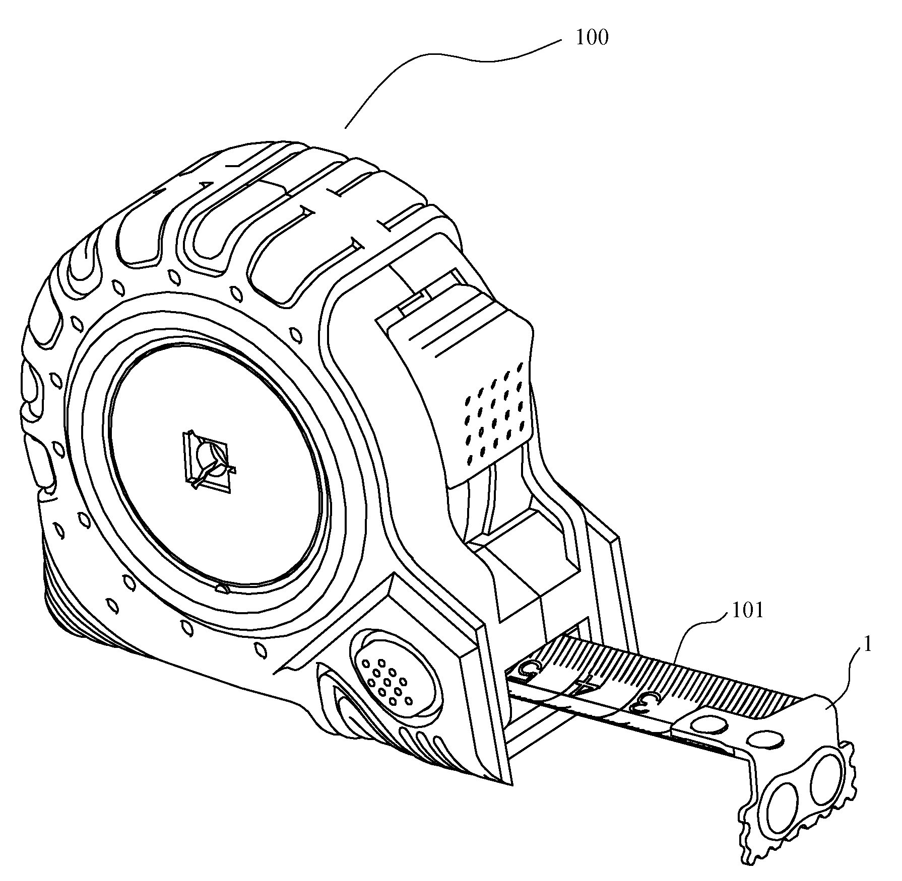
a technology of end hooks and tape measures, applied in the field of tape measures, can solve the problems of changing the thickness of the end hook, the difficulty of precisely mounting the magnet by riveting or adhesion, and the possibility of falling or breaking, so as to improve the efficiency of manufacture and ensure the exactness of assembly. , the effect of reducing the probability of falling or breaking

Inactive Publication Date: 2009-11-26
ZHOU XIAOGANG
View PDF12 Cites 24 Cited by
  • Summary
  • Abstract
  • Description
  • Claims
  • Application Information

AI Technical Summary

Benefits of technology

[0016]It is an object of the present invention to provide a magnetic end hook for tape measure whose components can be set firmly and are easy to assemble, and furthermore to reduce the probability of breaking the magnet.
[0027]And the gasket has a strip-shaped bulge between the adapted holes or grooves and said vertical portion has a strip-shaped hole correspondingly to receive and fix the strip-shaped bulge. This design makes the magnet joint with the end hook more firmly.
[0038]Compared with the prior art, in this invention, the gasket additionally set between the hole of the end hook and the magnet on the magnetic end hook is resilient and can adjust the preferred distance between the magnet and the inner wall of the hole. Therefore, the magnet is mounted more firmly and the probability of falling or breaking is reduced. Furthermore, the strip-shaped bulge on the gasket makes the magnet joint with the end hook more firmly. More importantly, the gasket and the magnet can be fixed on the vertical portion of the main body of the end hook together through plastic injection with the magnet as a metal insert. It not only greatly improves the efficiency of manufacture, but also ensures the exactness of assembly.

Problems solved by technology

However, the existing problems in those solutions are as follows: Firstly, most of the magnets with strong magnetism are manufactured by powder metallurgy such as Nd—Fe—B which is not suitable for riveting; Secondly, the magnet mounted on the end hook by adhering is not firm enough, the magnet will probably loose from the end hook after long time using; Thirdly, the magnet is difficulty to be mounted exactly by riveting or adhering, and it will change the thickness of the end hook and effect the exactness of measurement.
Firstly, no matter friction adapted or compression fitting, both require certain rigidity of the magnet, it is not suitable for the magnet with strong magnetism produced by powder metallurgy such as Nd—F—B, since the magnet will probably crash during the process of manufacture.
Secondly, even if to the magnet with enough rigidity, no matter friction fitting or compression fitting, the joint area between the magnet and the end hook is still small limited by the thickness of the end hook, and the magnet will probably fall under the strong outside force such as crash or squeeze.
Thirdly, it is difficult to ensure the front surface and the rear surface of the magnet separately being part of the front surface and the rear surface of the end hook during the process of manufacture. Even if it can be done, the efficiency of manufacture will be low.

Method used


Image

  • Magnetic End Hook for Tape Measure, Manufacture Method and Application Thereof
  • Magnetic End Hook for Tape Measure, Manufacture Method and Application Thereof
  • Magnetic End Hook for Tape Measure, Manufacture Method and Application Thereof

Examples


first embodiment

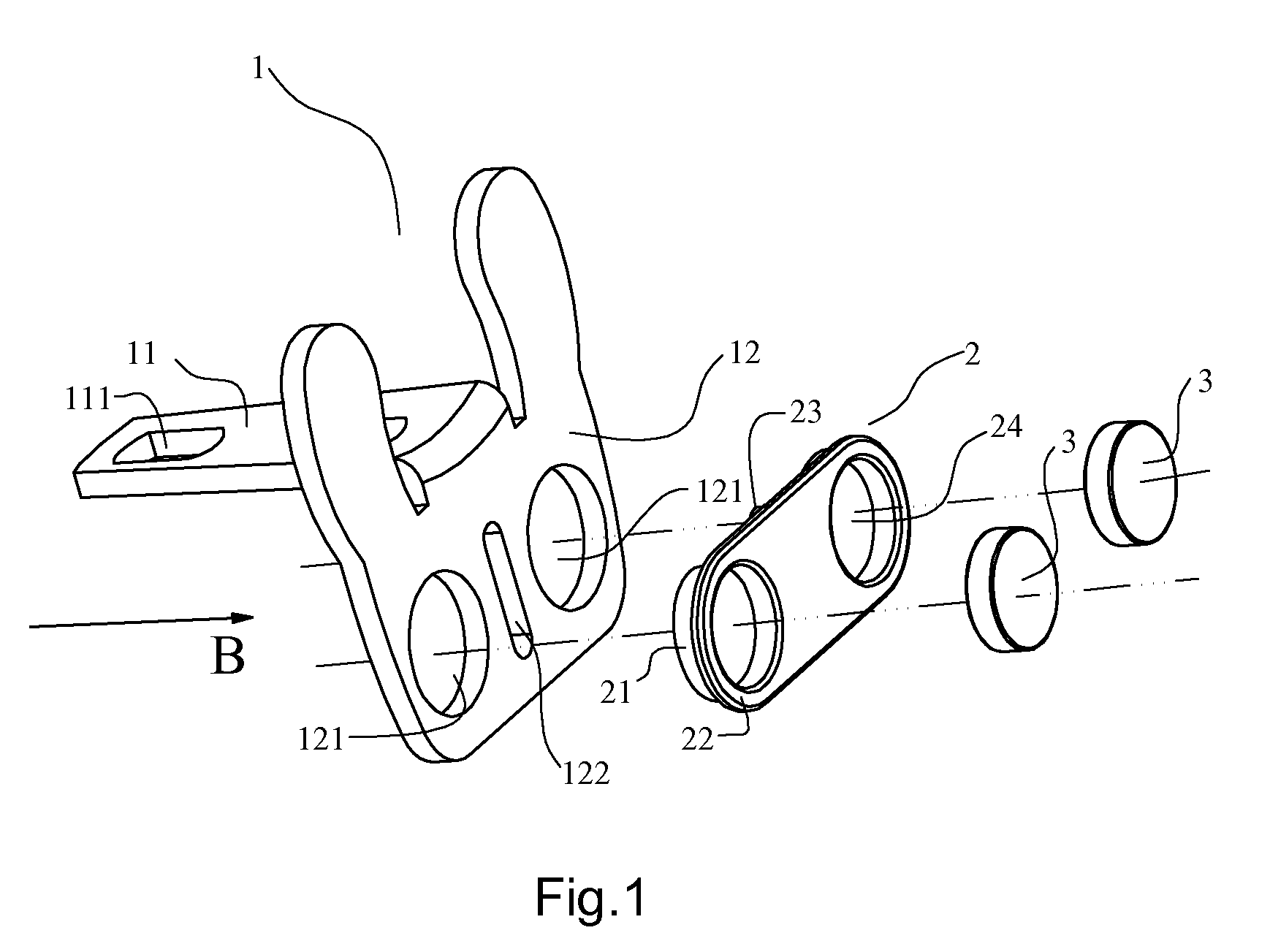
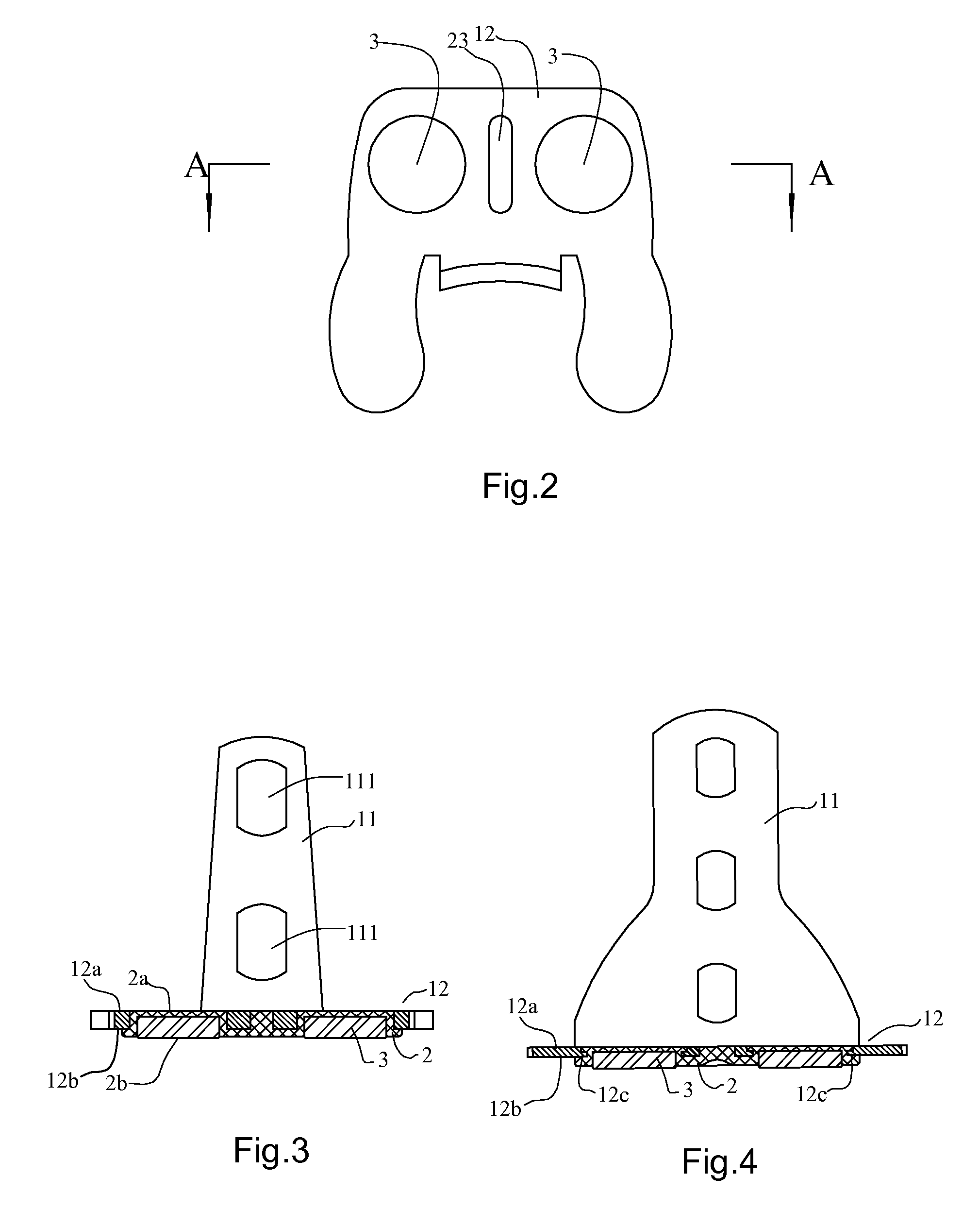
[0054]FIGS. 1-3 show the present invention.

[0055]In this embodiment, the magnetic end hook for tape measure comprises two magnets 3, a main body 1 of end hook and a gasket 2. The main body 1 of end hook comprises a horizontal portion 11 jointed with a tape blade and a vertical portion 12. The horizontal portion 11 has a pair of eyelets 111 for the end hook being mounted on the tape blade, and the vertical portion 12 has a pair of holes 121 for setting the magnets 3, furthermore, the vertical portion 12 includes a front surface 12b and a rear surface 12a. While, the magnets 3 are exposed and protrude from the front surface 2b of the gasket 2, and the magnets 3 are not exposed at the rear surface 2a of the gasket 2.

[0056]The gasket 2 comprises two inserting portions 21 which separately locate in the holes 121 on the end hook and two extending portions 22 projecting outward for leaning on the surface of the vertical portion 12. The gasket 2 has a strip-shaped bulge 23 between the two i...

second embodiment

[0058]FIG. 4 shows the present invention.

[0059]The difference of this embodiment compared with the first embodiment is that each hole 121 of the magnetic end hook has ring-shaped rib 12c on its inner wall, correspondingly, the gasket 2 has ring-shaped grooves to receive the ring-shaped ribs 12c respectively.

third embodiment

[0060]FIG. 5 shows the present invention.

[0061]The difference of this embodiment compared with the first embodiment is that each magnet 3 is sunk in the adapted groove 24 of the gasket 2 and is encircled with the edge of the adapted groove 24.


PUM


Abstract

A magnetic end hook on tape measure, comprises a magnet (3) and a main body (1) of the end hook which includes a horizontal portion (11) jointed with a tape blade, a vertical portion (12) having a front surface (12b), a rear surface (12a) and at least one hole (121) for setting said magnet (3); wherein the magnetic end hook further comprising an gasket (2), said gasket has an adapted hole or groove (24) for receiving said magnet (3). A method of manufacture and an application are also described. Compared with the prior art, in this invention, the gasket, additionally set between the hole of the end hook and the magnet on the magnetic end hook, is resilient and can adjust the preferred distance between the magnet and the inner wall of the hole. Therefore, the magnet is mounted more firmly and the probability of falling or breaking is reduced.

Description

FIELD OF THE INVENTION[0001]The present invention relates to the field of tape measure and its manufacture, in particular, to a magnetic end hook for tape measure and method of manufacture therefore, and the tape measure with the magnetic end hook.DESCRIPTION OF THE PRIOR ART[0002]Tape measure is an usual tool to measure a long distance which is generally above 20 cm. It generally includes a housing, a coiled tape blade mounted in the housing, and the end of the tape blade is bended, which is called as end hook. The end hook has three functions: first of all, it can be blocked at the opening of the housing to prevent the tape blade completely retracting into the housing; Secondly, it is convenient for user to pull the tape blade out by fingers; Thirdly, the start position of the measurement can be hooked by the end hook so that even one person can do the measurement.[0003]However, not all of the start position of the measurement can be hooked by the end hook, for example, the start ...

Claims


Application Information

Patent Timeline
Patent Type & Authority Applications(United States)
IPC IPC(8): G01B3/10
CPCG01B2003/1058G01B3/1056Y10S33/01
Inventor ZHOU, XIAOGANG
Owner ZHOU XIAOGANG
Learn More