Motor/generator structure

a brushless motor and generator technology, applied in the direction of dynamo-electric machines, electrical apparatus, magnetic circuit shapes/forms/construction, etc., can solve the problems of reducing the magnetic flux density, damaging the coils, and affecting the strength of the magnets, so as to improve the power conversion and increase the interaction

Inactive Publication Date: 2009-11-26
PRUCHER BRYAN
View PDF5 Cites 25 Cited by
  • Summary
  • Abstract
  • Description
  • Claims
  • Application Information

AI Technical Summary

Benefits of technology

[0017]Another object of the present invention is the provision of specially configured coil windings that overlap with one another and assemble to form a thin annular cylinder of a given diameter and substantially uniform thickness to provide electrical induction, and a cooling structure in the form of an array of angularly separated cooling pipes that nest within angular axially extending gaps formed by and between successive of the coil windings wherein to cool the coil winding segments during operation of the motor / generator, allow increased interaction between coils and magnets, and improve the power conversion with the motor or generator. The cooling pipes may comprise what are called heat pipes and are vapor phase heat transfer mechanisms that can transport large quantities of heat with a small difference in temperature between hotter and cooler interfaces. In connection with the radial gap motor according to this invention, the heat pipe can transport heat against gravity by an evaporation-condensation cycle.

Problems solved by technology

This gets around the problem of how to transfer current to a moving armature.
The maximum power that can be applied to a brushless motor is exceptionally high, limited almost exclusively by heat, which can damage the coils and affect the strength of the magnets.
While this arrangement allows closer packing of the working conductors, it also requires that the gap between the rotor's magnets and flux return be about twice as thick as would be required for a single thickness of a non-overlapping coil, thus reducing the magnetic flux density and thus reducing the motor's efficiency.
While believed useful for the purposes then desired, certain problems are believed to remain in an axial gap arrangement.
Because of these forces and possible adverse effects of heat build up during continued use, the magnets may break free.
Additional bonding material may be needed to overcome such situation, possibly resulting in increased cost and size of the structure.
However, such configuration suggests that some mechanism be provided to tolerate but not transfer heat from the coils during performance their electrical motor function.

Method used


Image

  • Motor/generator structure
  • Motor/generator structure
  • Motor/generator structure

Examples


Embodiment Construction

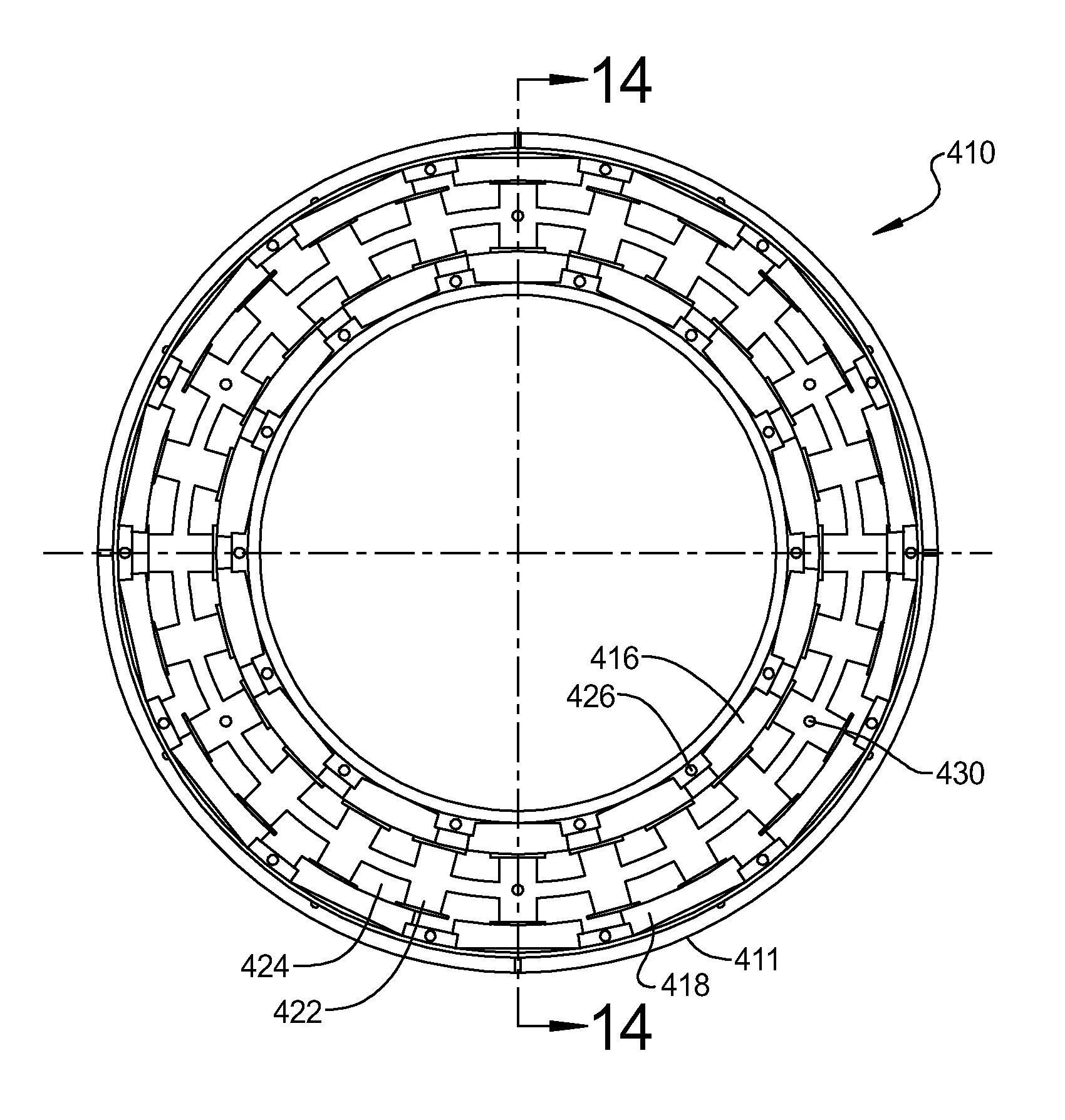
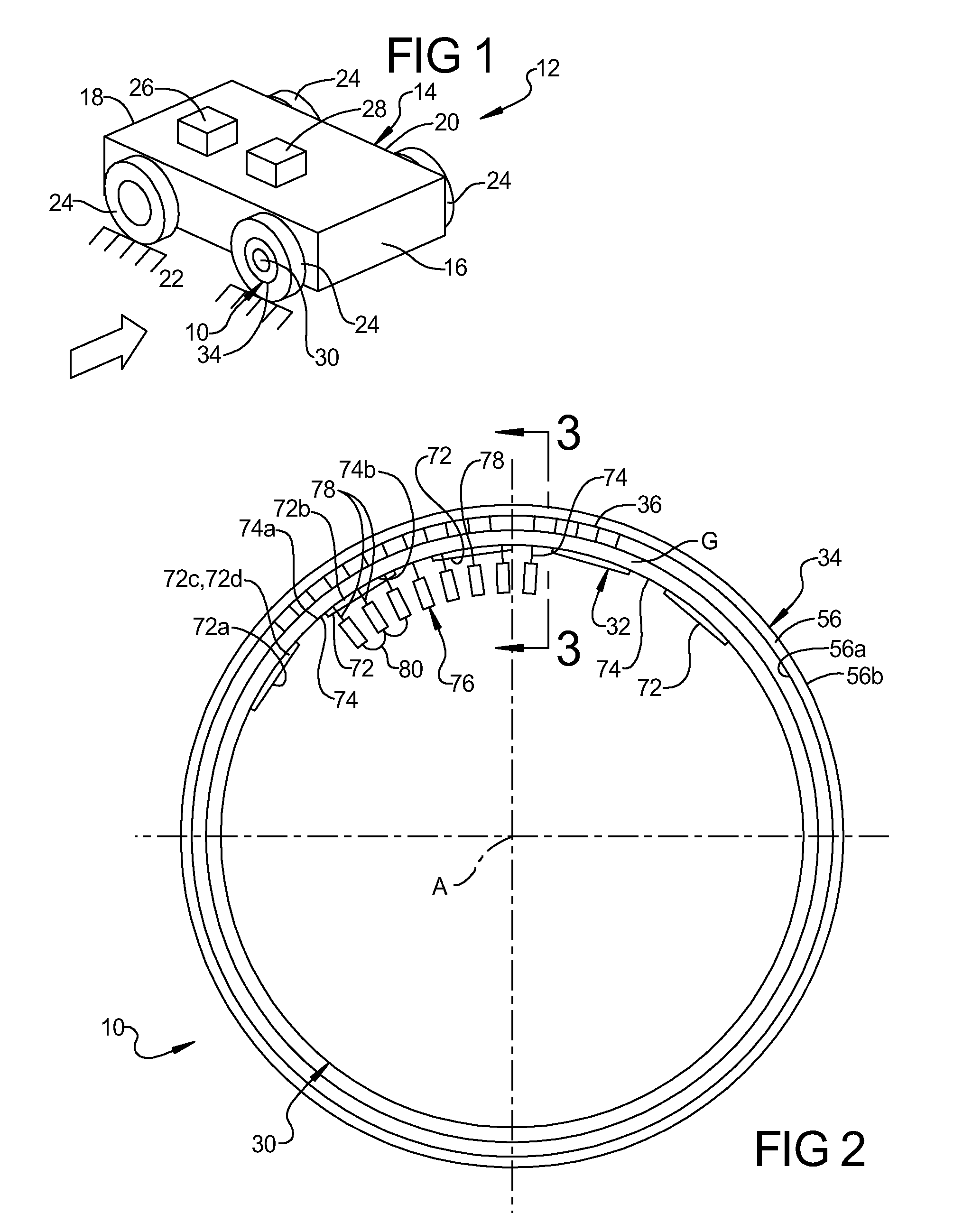
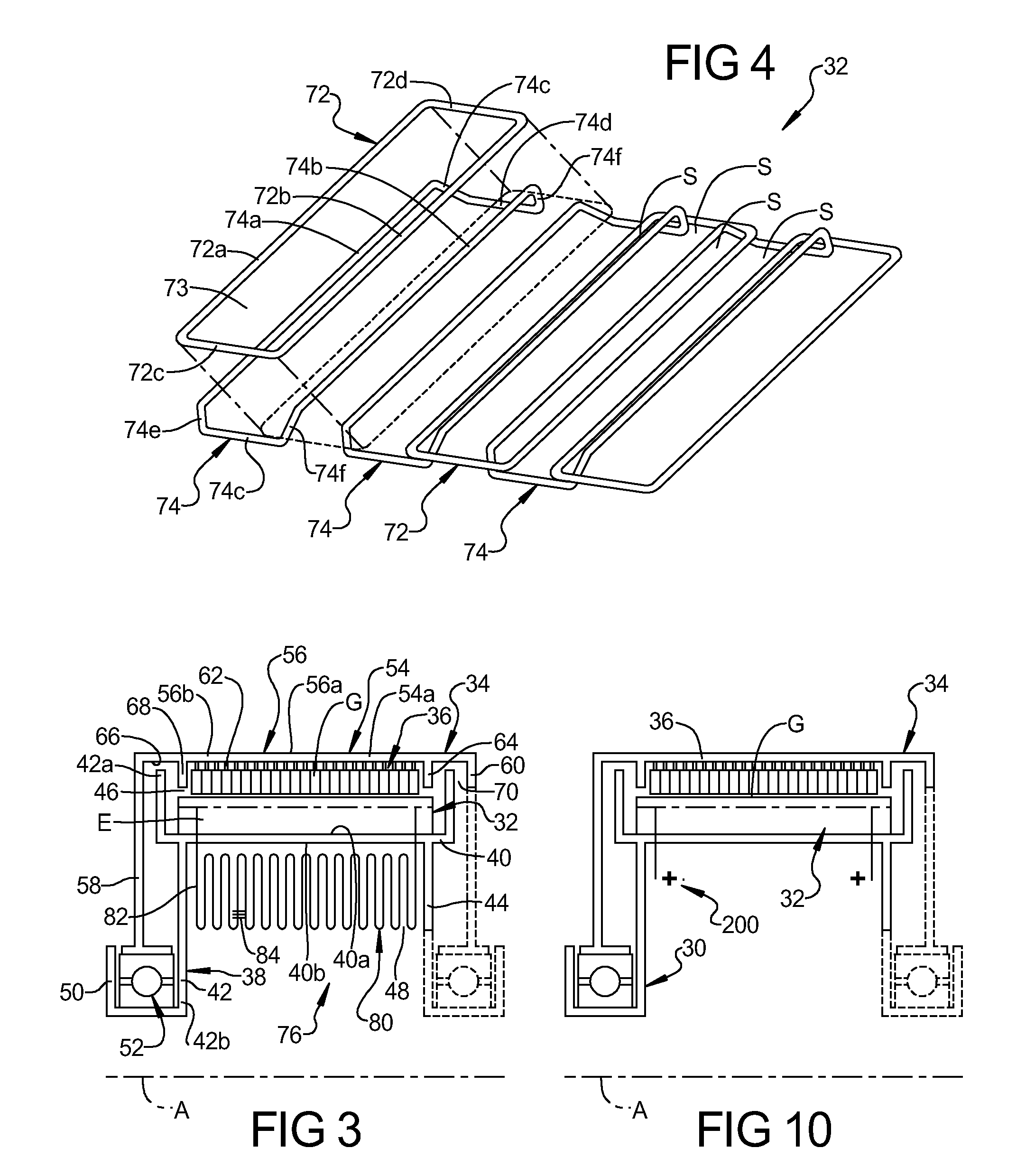
[0073]Referring now to the drawings, FIGS. 1-9 and FIG. 10, respectively, illustrate preferred embodiments of a brushless, ironless, synchronous, DC, single radial gap, electric motor or generator, according to this invention. As used herein, the apparatus of each embodiment is referred to as an electric motor, which produces mechanical power output in the form of rotational torque.

[0074]The electric motor of each embodiment includes a stator or stationary structure, a rotor mounted for rotation relative to the stator in a manner that a surface of the rotor is separated from a corresponding surface of the stator by a radial gap to form a cylindrical annular gap therebetween, a succession of permanent magnets, or annular magnet structure, is mounted to a surface of the rotor for rotation therewith and in juxtaposed relation with an electromagnetic induction structure mounted to a surface of the stator.

[0075]In the embodiments described herein, the rotor and magnet structure rotate ab...


PUM


Abstract

A radial gap motor/generator has a thin annular array of magnets mounted for rotation to a stator in a radially spaced relation to at least one thin annular induction structure fixed to a stationary stator may be air or liquid cooled. Further, the motor has at least radial gap between a magnetic core and the array and may include multiple gaps and multiple annular induction structures to increase the overall power density of the system.

Description

CROSS-REFERENCE TO RELATED APPLICATIONS[0001]This application is a continuation application of co-pending U.S. Patent Application No. 61 / 128,326 filed May 21, 2008 for “MOTOR / GENERATOR STRUCTURE” the entire disclosure of which is hereby incorporated by reference, including all text and drawingsBACKGROUND OF THE INVENTION[0002]1. Field of the Invention[0003]This invention relates generally to brushless rotary electrical motor / generator structures for producing an output voltage or mechanical power output in the form of rotational torque such as for use in rotating the wheel of a vehicle and propelling the vehicle; and more specifically, to a radial gap motor / generator wherein at least one thin annular array of magnets is mounted for rotation to a rotor in radially spaced relation to at least one thin annular induction structure fixedly arranged on a stationary stator. Even more particularly, the present invention is directed to a cooling arrangement or structure for transferring heat...

Claims


Application Information

Patent Timeline
Patent Type & Authority Applications(United States)
IPC IPC(8): H02K1/06H02K9/20
CPCH02K9/005H02K3/47H02K9/00
Inventor PRUCHER, BRYAN
Owner PRUCHER BRYAN
Why Eureka
Try Eureka