Fluidized Bed Heat Exchanger for a Circulating Fluidized Bed Boiler and a Circulating Fluidized Bed Boiler with a Fluidized Bed Heat Exchanger

a technology of fluidized bed and heat exchanger, which is applied in the direction of fluidized bed combustion apparatus, lighting and heating apparatus, and boilers with circulating fluids. it can solve the problems of insufficient heat exchange efficiency of heat exchanger, and insufficient efficiency and flexibility of heat exchanger in all operating conditions of the boiler

Active Publication Date: 2009-12-03
FOSTER WHEELER ENERGIA OY
View PDF11 Cites 8 Cited by
  • Summary
  • Abstract
  • Description
  • Claims
  • Application Information

AI Technical Summary

Benefits of technology

[0008]An object of the present invention is to provide a heat exchanger, to be arranged in the external hot circulation path of a circulating fluidized bed boiler, for reducing the above-mentioned drawbacks of prior art heat exchangers of the circulating fluidized bed boiler.

Problems solved by technology

Increasing the height of the fluidized bed increases the pressure loss of the fluidizing gas, and increasing its width and depth may lead to disadvantageous solutions in view of the structure or space consumption.
Thus, the heat exchange efficiency of the heat exchanger, and the adjustability of the heat exchange efficiency, may be inadequate, especially at low loads.
The adjustability of this kind of a heat exchanger is quite good, but even here, the efficiency and flexibility of the heat exchanger are not necessarily sufficient in all operational conditions of the boiler.

Method used


Image

  • Fluidized Bed Heat Exchanger for a Circulating Fluidized Bed Boiler and a Circulating Fluidized Bed Boiler with a Fluidized Bed Heat Exchanger
  • Fluidized Bed Heat Exchanger for a Circulating Fluidized Bed Boiler and a Circulating Fluidized Bed Boiler with a Fluidized Bed Heat Exchanger
  • Fluidized Bed Heat Exchanger for a Circulating Fluidized Bed Boiler and a Circulating Fluidized Bed Boiler with a Fluidized Bed Heat Exchanger

Examples


Embodiment Construction

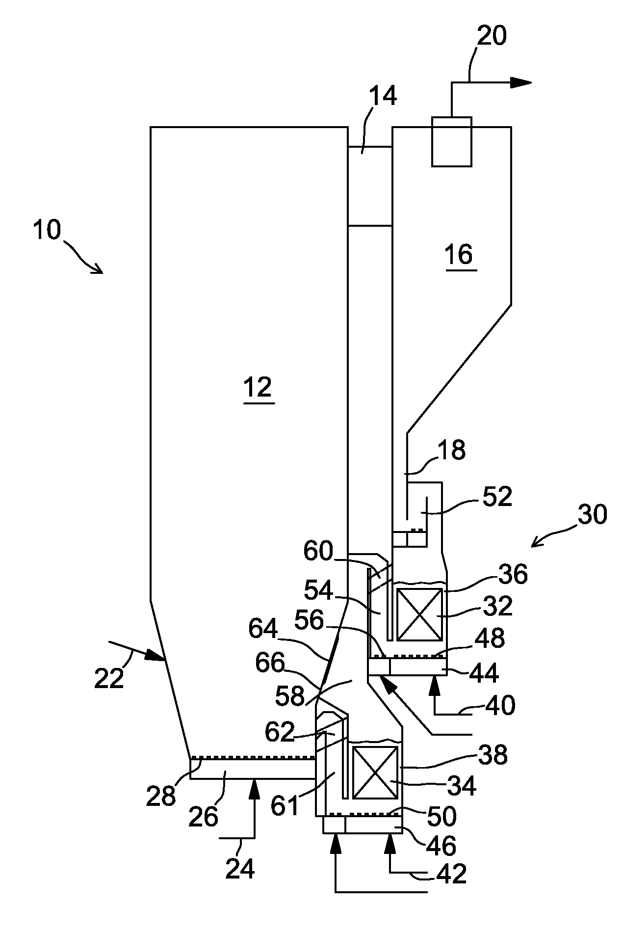
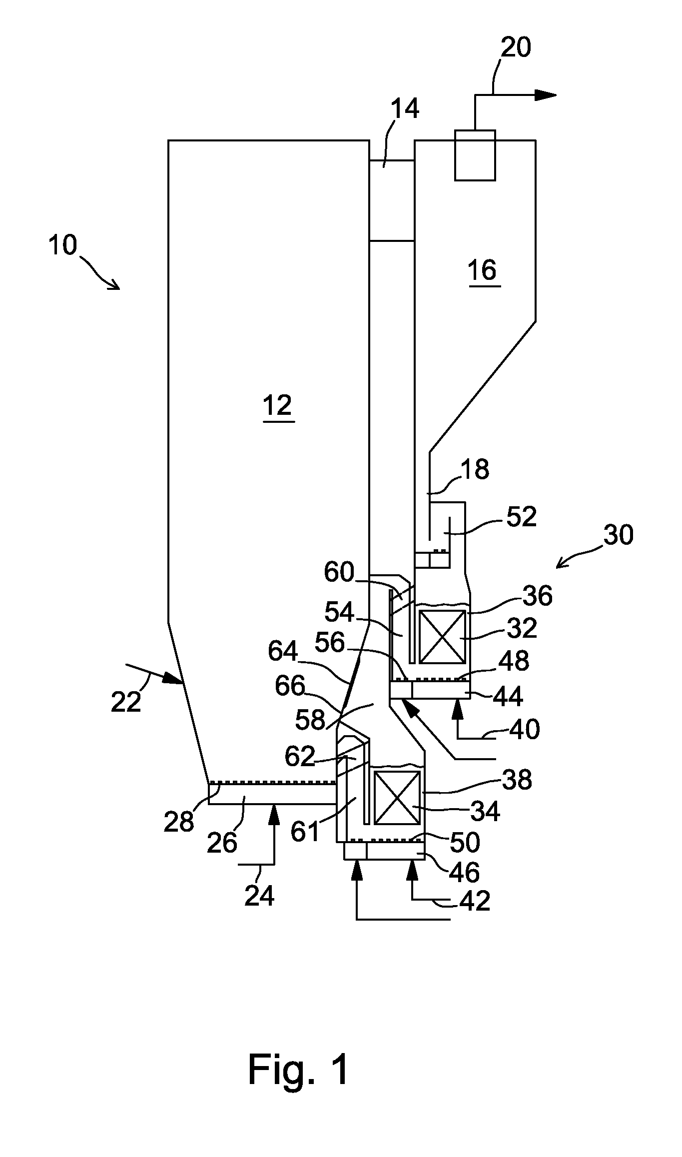
[0022]FIG. 1 illustrates a CFB boiler 10 in accordance with a preferred embodiment of the present invention, which boiler comprises a furnace 12, an outlet channel 14 connected with the upper section of the furnace 12, a particle separator 16 for external hot circulation, connected with the outlet channel 14, the lower portion of the particle separator 16 being joined with a return channel 18, which returns the solids separated with particle separator 16 to the lower section of the furnace 12, and the upper portion of the particle separator 16 being joined with a flue gas duct 20 for removing cleaned flue gas to the backpass of the boiler 10, the gas cleaning device and further, through the stack to the environment. (As the last mentioned devices are known from the prior art, and as they are not specifically part of the present invention, they are not shown in FIG. 1.) The CFB boiler 10, for example, may be of a natural circulation type or a supercritical once through utility (OTU) ...


PUM


Abstract

A heat exchanger and a circulating fluidized bed boiler with a heat exchanger including a first fluidized bed heat exchange chamber and a second fluidized bed heat exchange chamber, arranged in connection with a furnace of the circulating fluidized bed boiler, a first inlet channel for introducing hot solids from a particle separator of the external circulation of the circulating fluidized bed boiler into the first heat exchange chamber, a second inlet channel for introducing solids to the second heat exchange chamber, a first discharge for removing a first portion of the cooled solids from the first heat exchange chamber to the second inlet channel and a second discharge for removing cooled solids from the second heat exchange chamber to the furnace, the heat exchange chamber including an inlet for introducing hot solids directly from the internal circulation of the furnace to the second heat exchange chamber. The heat exchanger also preferably includes a third discharge for removing a second portion of the cooled solids from the first heat exchange chamber directly to the furnace.

Description

[0001]This application is a U.S. national stage application of PCT International Application No. PCT / FI2007 / 050264, filed May 9, 2007, published as PCT Publication No. WO 2007 / 128883 A2, and which claims priority from Finnish patent application number 20065308, filed May 10, 2006.FIELD OF THE INVENTION[0002]The present invention relates to a fluidized bed heat exchanger for a circulating fluidized bed boiler (CFB boiler), and to a circulating fluidized bed boiler with such a heat exchanger. More specifically, the invention relates to the external hot circulation of the CFB boiler, in other words, to an efficient heat exchanger arranged in the return channel for solids, which have been separated from the exhaust gas of the CFB boiler by a particle separator, and which are to be returned to the furnace. The invention especially relates to arranging an efficient heat exchanger in a supercritical once-through utility boiler (OTU boiler), which is provided with reheating.BACKGROUND OF TH...

Claims


Application Information

Patent Timeline
Patent Type & Authority Applications(United States)
IPC IPC(8): F22B27/14F23J3/00F23C10/04F22B31/08
CPCF22B31/0092F23C2206/103F23C10/32F23C10/04F22B31/00F23C10/00
Inventor KAUPPINEN, KARI
Owner FOSTER WHEELER ENERGIA OY
Why Eureka
Try Eureka