Variable Stiffness Spoke For a Non-Pneumatic Assembly

a non-pneumatic and variable stiffness technology, applied in the direction of tyre parts, wheel attachments, transportation and packaging, etc., can solve the problems of limiting static vertical deflection, affecting the average contact pressure between the outer band and the loading surface, and high stiffness, so as to reduce the stress concentration

Inactive Publication Date: 2009-12-03
MICHELIN RECH & TECH SA +1
View PDF24 Cites 44 Cited by
  • Summary
  • Abstract
  • Description
  • Claims
  • Application Information

AI Technical Summary

Benefits of technology

[0004]The invention described herein provides a non-pneumatic deformable structure having a variable stiffness spoke assembly that provides a method of adjusting the vertical stiffness. Another advantage of the invention is to reduce the stress concentration, which may develop at the ends of the spoke.

Problems solved by technology

In this instance, the high stiffness limits the static vertical deflection.
However, this also affects the average contact pressure between the outer band and the loading surface, which is an important overall design criterion for a specific application.

Method used


Image

  • Variable Stiffness Spoke For a Non-Pneumatic Assembly
  • Variable Stiffness Spoke For a Non-Pneumatic Assembly
  • Variable Stiffness Spoke For a Non-Pneumatic Assembly

Examples


Embodiment Construction

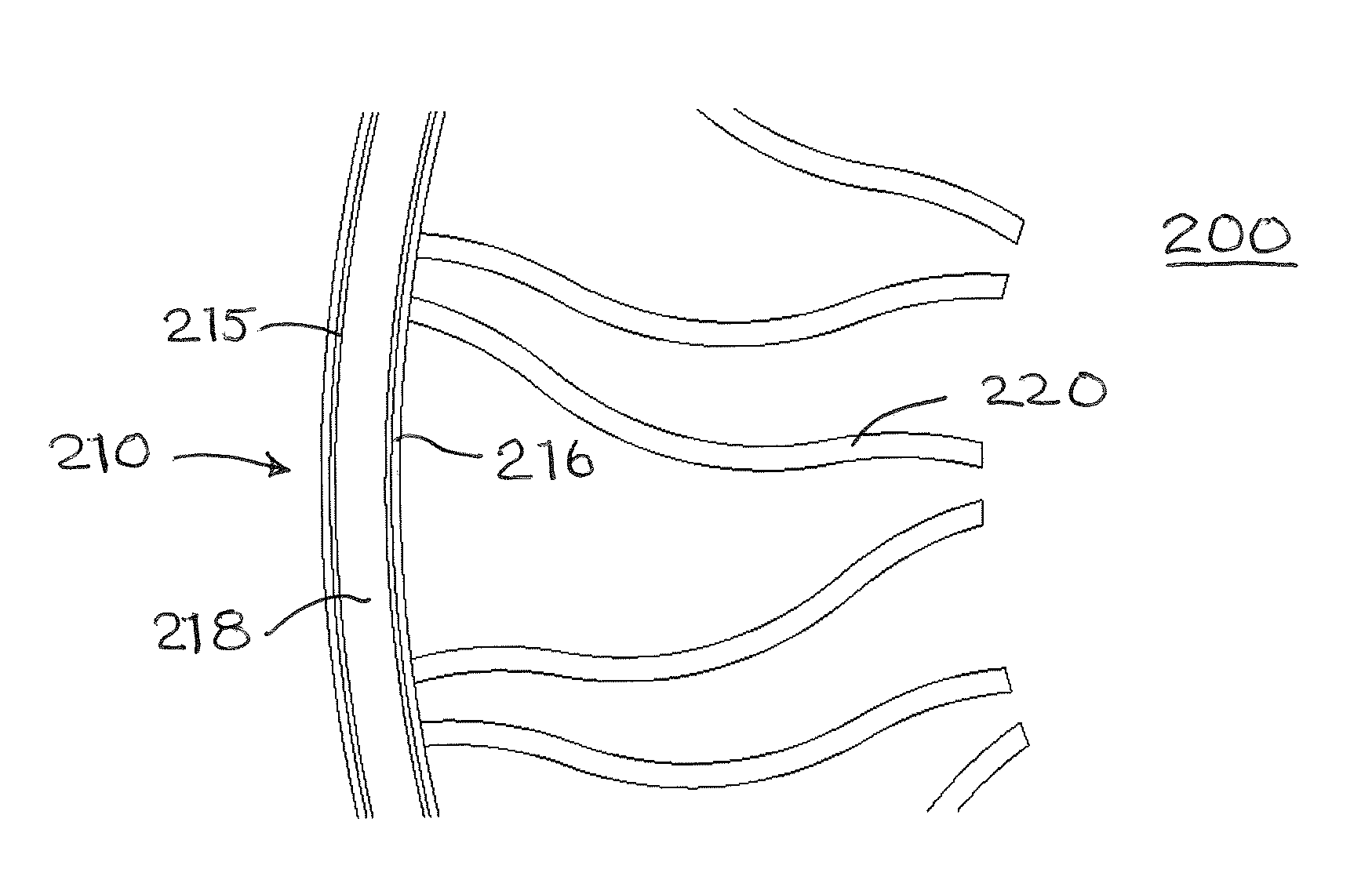
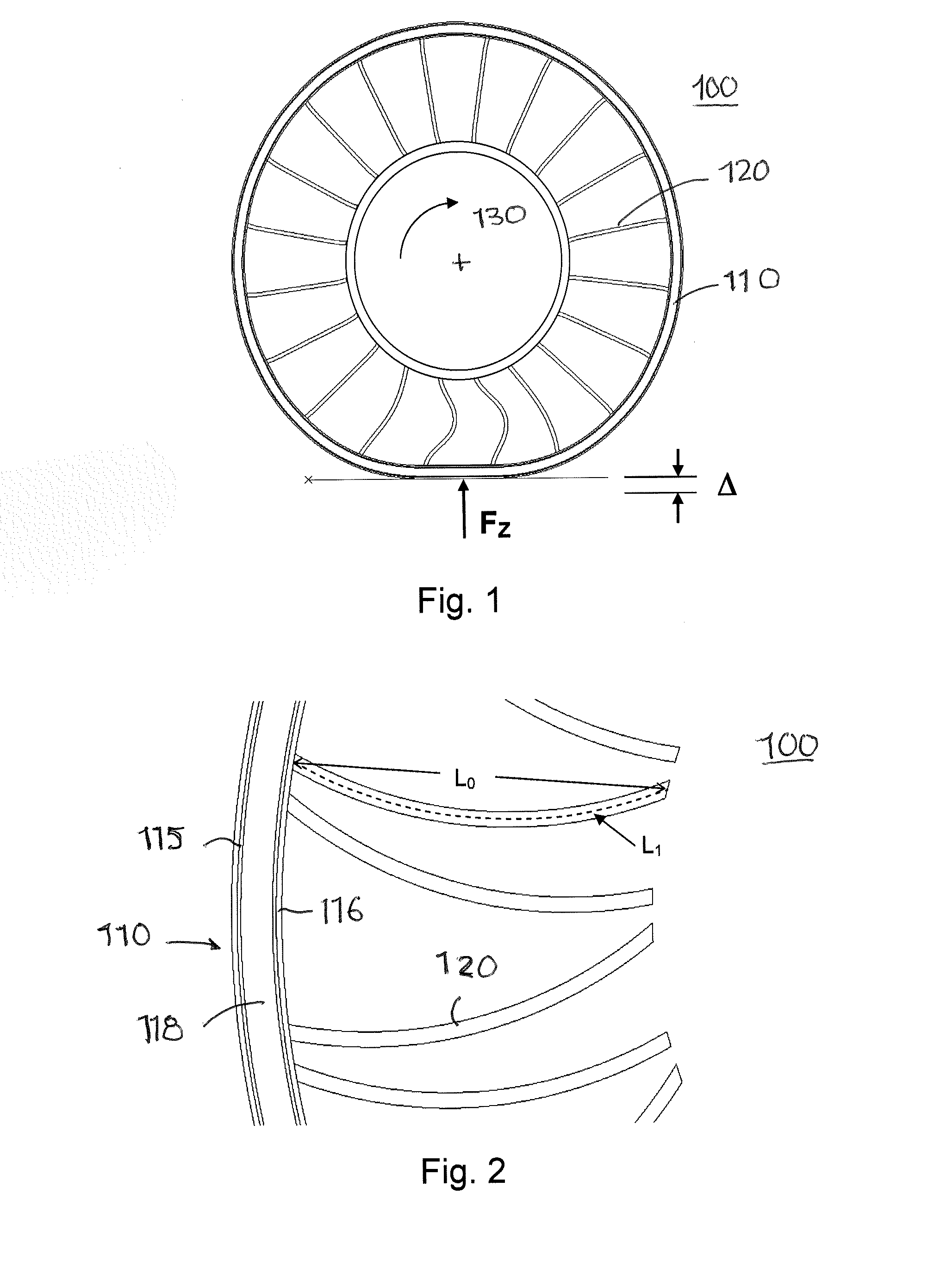
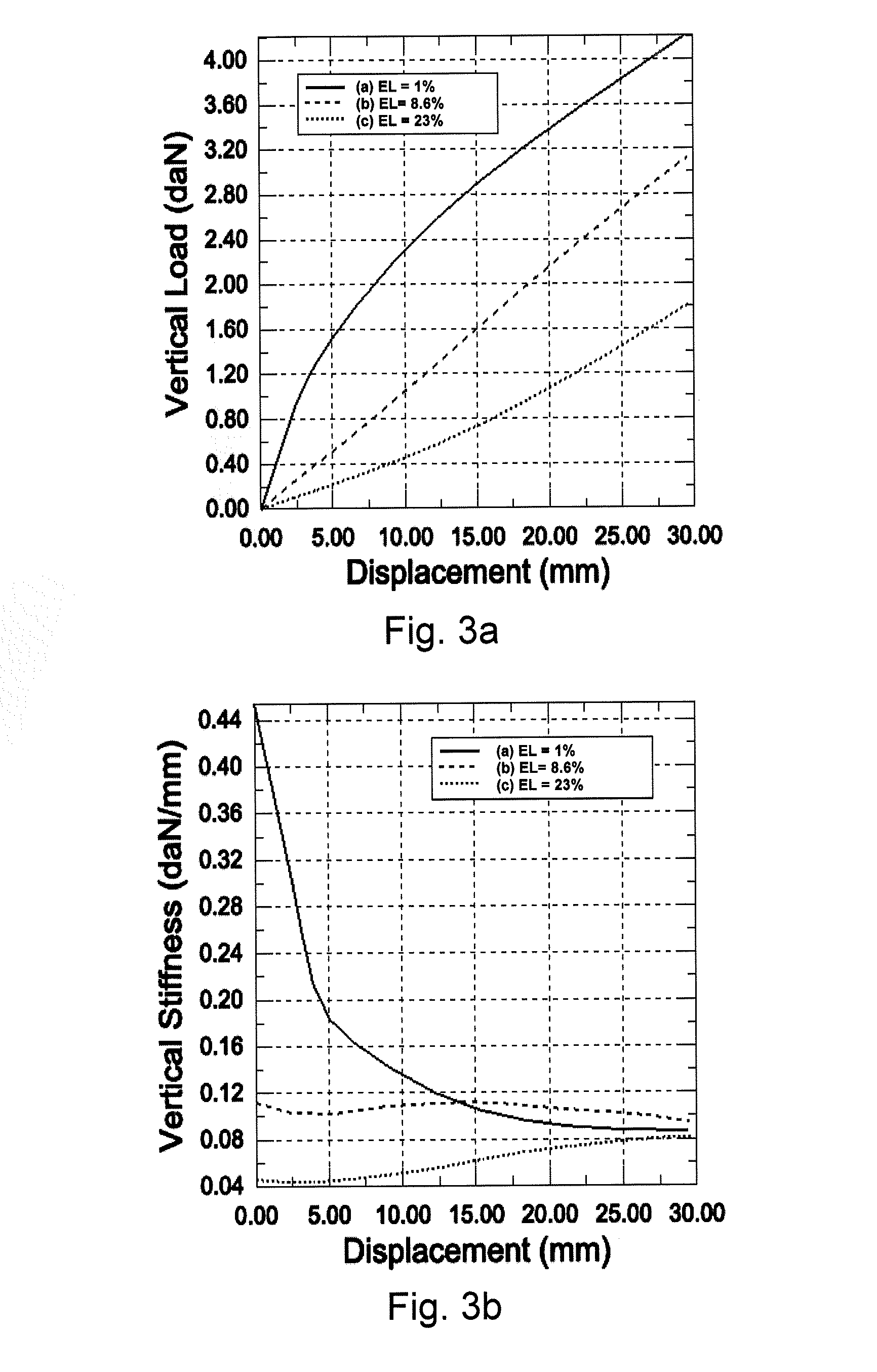
[0021]FIG. 1 is an example of a non-pneumatic deformable structure 100. The structure comprises an outer band 110 having a predetermined stiffness. A set of spoke-like elements 120 connect the band 110 to a hub 130. The hub 130 may then be attached to a vehicle axle or other apparatus capable of rotation about an axis. The stiffness of the band may be obtained through various types of reinforcements in single or multiple layers. U.S. Pat. Nos. 7,013,939 and 6,769,465 provide examples of suitable band constructions and design information to obtain a desired load carrying capability. FIG. 1 illustrates the application of a vertical load FZ to the non-pneumatic structure 100 under conditions where the hub 130 is held vertically immovable. The portion of the outer band 110 in contact with the ground undergoes an upward vertical displacement Δ. FIG. 3a is a graphical representation of the force FZ (in daN) versus vertical displacement delta for three levels of excess length EL (described...


PUM


Abstract

The invention described herein provides a non-pneumatic deformable structure having a variable stiffness spoke assembly that provides a method of adjusting the vertical stiffness. The structure comprises an outer annular band having a predetermined stiffness, a set of spoke elements having an outer end and an inner end, where the outer end is connected to the outer band, with the spoke element extending inward and having its inner end connected to a hub, the hub being configured to attach the structure to a vehicle axle or other apparatus capable of rotation about an axis. Each of the spoke elements has a curvilinear length greater than the length of a straight line segment extending from a point of connection of the outer end of the spoke element with the outer annular band to a point of connection of the inner end of the spoke element to the hub. The outer end of said spoke element is tangent to the straight line segment, and the inner end of said spoke element is tangent to the straight line segment.

Description

BACKGROUND[0001]Non-pneumatic deformable structures for use in the support of loads under rolling conditions, such as to support loads for automotive vehicles have been described, for example in U.S. Pat. No. 7,201,194, which is commonly owned by the assignee of the current invention. The structurally supported, non-pneumatic tire disclosed therein includes a reinforced annular band that supports the load and a plurality of web spokes that transmit in tension the load forces between the annular band and a wheel or hub. The tire supports its load solely through the structural properties and, contrary to the mechanism in pneumatic tires, without support from internal air pressure.[0002]In the exemplary structure shown in FIG. 1 herein, the spokes are shown as radially-oriented elements, which then extend more or less transversely across the width of the non-pneumatic deformable structure. The structure acts as a “top loading” structure meaning that the vertical load applied from the g...

Claims


Application Information

Patent Timeline
Patent Type & Authority Applications(United States)
IPC IPC(8): B60B9/26
CPCB60C7/18B60B9/26
Inventor CRON, STEVEN M.
Owner MICHELIN RECH & TECH SA
Why Eureka
Try Eureka