
System for and method of projection weld-bonding workpieces

Inactive Publication Date: 2009-12-03
GM GLOBAL TECH OPERATIONS LLC
View PDF15 Cites 20 Cited by
  • Summary
  • Abstract
  • Description
  • Claims
  • Application Information

AI Technical Summary

Benefits of technology

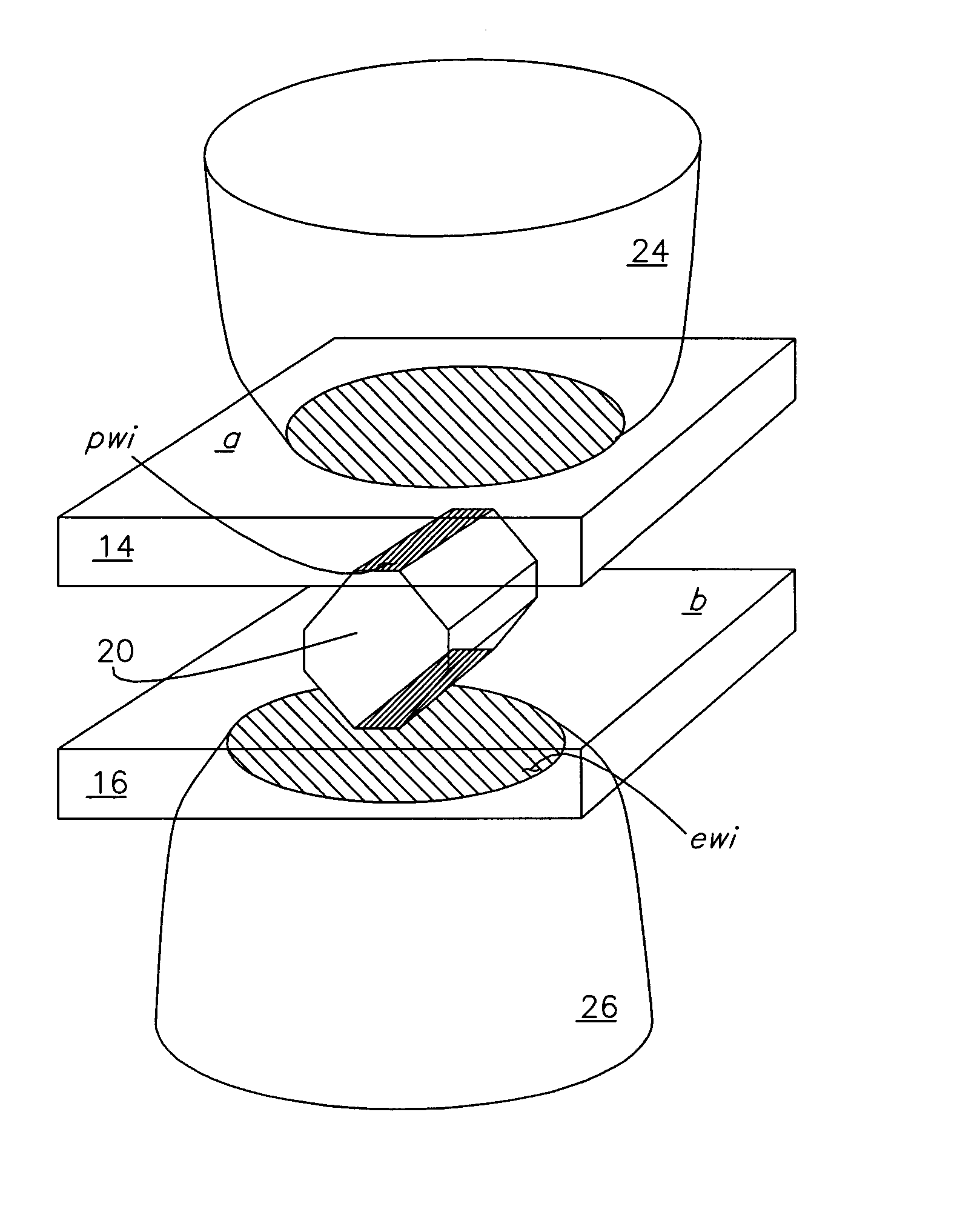
[0011]Responsive to this need, an improved method of weld-bonding a plurality of similar or dissimilar workpieces that eliminates exterior surface anomalies is presented. The method involves the use of an adhesive layer having a plurality of projections embedded therein. The inventive system and method disclosed herein is useful among other things for providing a facilely implemented solution that requires no new or additional resistance welding equipment.
[0012]The method is useful for producing invisible fusion welds, which makes it ideal for exterior product welds (i.e., welds wherein the exterior surface of one or both of the engaged workpieces present an exterior product surface). It is appreciated that decreasing the amount of and more preferably eliminating exterior surface anomalies reduces the need for and extent of a finishing process, and thereby results in a reduction of the afore-mentioned costs.
[0013]The method is further useful for providing a sealed joint that forms a barrier to outside contaminants, such as oil, grease, water, and particulate matter. The inventive method produces a combined welded and adhesively bound joint that presents greater structural strength in comparison to welding or adhesive bonding individually. Where used in an automotive setting, such as roof deck construction, it is also appreciated that the invention produces better weld quality in that a larger bonding area is realized, and enables the roof ditch width to be reduced. Finally, it is appreciated that the inventive process of embedding a plurality of projections in a layer of adhesive material eliminates the time consuming need to fabricate the projections, and thereby eliminates the need for a fabrication station and / or hardware.

Problems solved by technology

Undesirably, however, exterior anomalies and aesthetic concerns are also often experienced.
Invariably, however, these finishing processes result in increased costs, including but not limited to additional material and labor.
The need to address aesthetic concerns also results in a longer period of manufacture, thereby impacting productivity.
Even where a finishing process is provided, traces of the exterior anomalies remain and are often easily detectable through the paint.
It is appreciated, however, that these methods present more complex and therefore costly technologies in comparison to conventional resistance welding.
As such, these technologies have achieved limited market penetration and are relegated to relatively small subsets of applications.
However, it is also appreciated that this method of joining typically provides lower overall strength in comparison to welded joints.

Method used


Image

  • System for and method of projection weld-bonding workpieces
  • System for and method of projection weld-bonding workpieces
  • System for and method of projection weld-bonding workpieces

Examples


Embodiment Construction

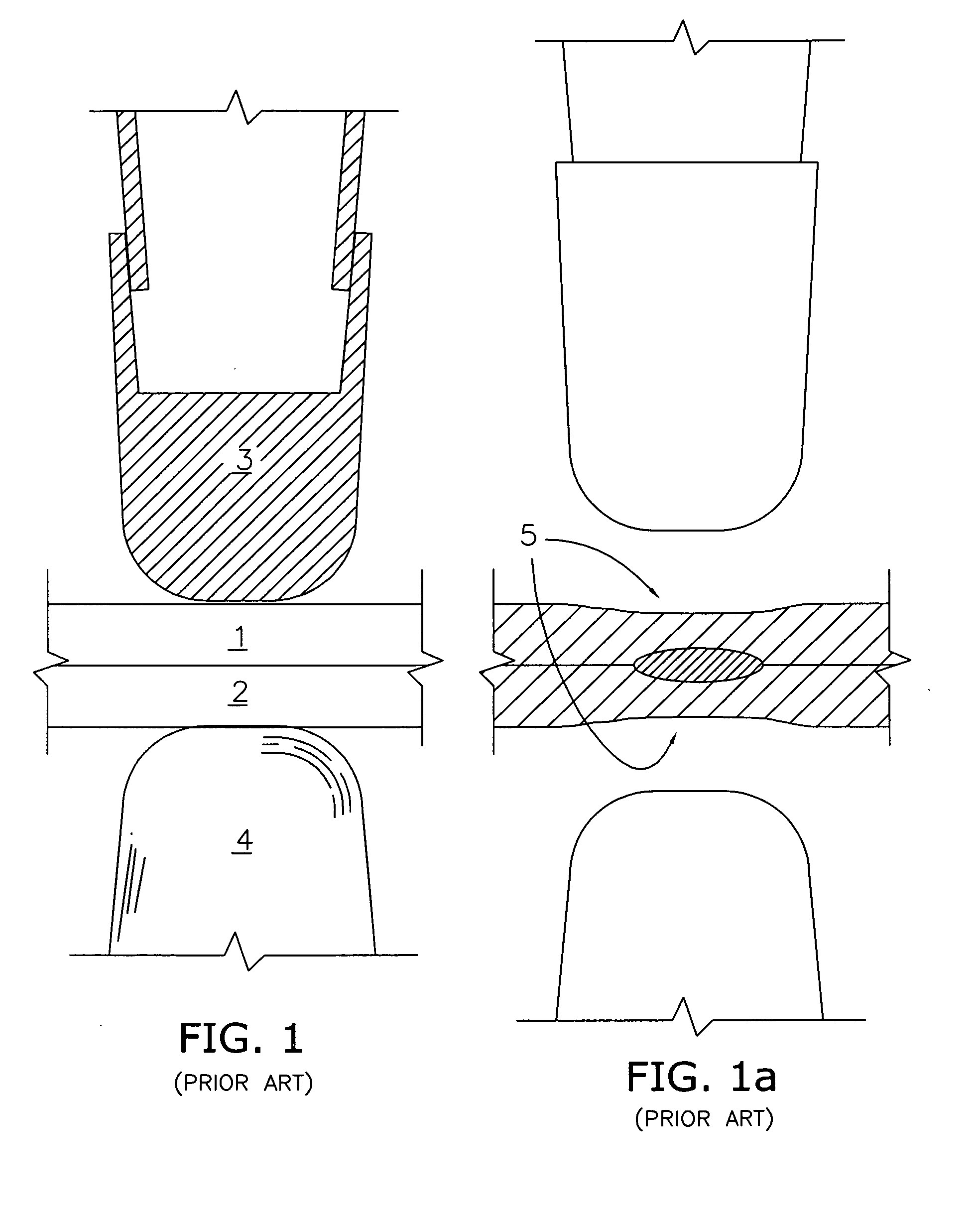
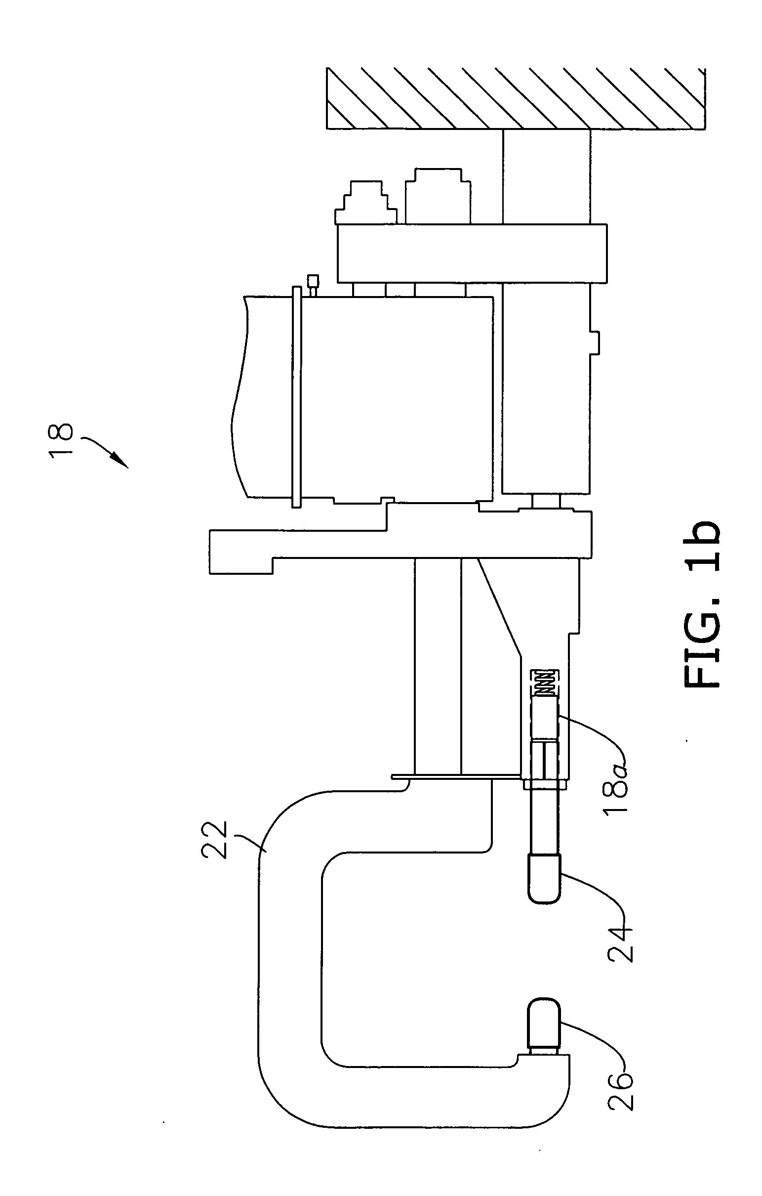
[0040]The present invention concerns a system 10 (FIGS. 2-13b) for and method of producing an invisible spot or seam weld 12 (FIG. 3) between a plurality of workpieces 14,16, such as a two-sheet “stack-up” of automotive sheet metal. The inventive system 10 is configured to produce the invisible weld 12 respective to the exterior of the constructed workpiece assembly (compare FIGS. 1a and 2b). That is to say, exterior surface deformations or anomalies, such as surface depressions, are not formed during the inventive resistance welding method described herein. It is appreciated that the invention, therefore, increases the aesthetic appeal and reduces manufacturing costs associated with the assembled product. The invention is adapted for use with conventional resistance mash welding devices, such as the apparatus 18 generally depicted in FIG. 1b, and does not require additional welding equipment and / or modifications.

[0041]In the illustrated embodiments, a plurality of two workpieces 14...


PUM

PropertyMeasurementUnit
Fractionaaaaaaaaaa
Diameteraaaaaaaaaa
Lengthaaaaaaaaaa

Abstract

A system for and method of projection weld-bonding a plurality of workpieces, includes the steps of securing at least one adhesive layer having a plurality of projections embedded therein intermediate the workpieces, and engaging the workpieces with a resistance welding apparatus such that only the projections fuse to form the weld pool, and the layer cures to form an adhesive seal around the welds, together the adhesive layer and projections cooperatively forming a reinforced joint.

Description

CROSS-REFERENCES TO RELATED APPLICATIONS[0001]This U.S. Non-Provisional patent application claims the benefit of and is a continuation-in-part from pending U.S. Non-Provisional application Ser. No. 11 / 937,518, entitled SYSTEM FOR AND METHOD OF PRODUCING INVISIBLE PROJECTION WELDS filed on Nov. 9, 2007.BACKGROUND OF THE INVENTION[0002]1. Field of the Invention[0003]The present invention relates to resistance welding systems and bonding methods, and more particularly concerns a resistance welding system for and method of weld-bonding a plurality of workpieces utilizing projections embedded within an adhesive layer.[0004]2. Discussion of Prior Art[0005]Resistance mash welding (e.g., conventional spot or seam welding) remains the most common method of joining metallic workpieces in various industries, including automotive manufacture and construction. In this method, the workpieces 1,2 are typically secured in a fixed condition, and then engaged by two electrodes 3,4, as shown in FIG. 1...

Claims


Application Information

Patent Timeline
IPC IPC(8): B23K11/00B32B3/00
CPCB23K2201/18B23K2203/04B23K2203/20Y10T428/24479B23K11/14B23K11/20B23K11/115B23K2101/18B23K2103/04B23K2103/20
Inventor KHAKHALEV, ALEXANDER D.
Owner GM GLOBAL TECH OPERATIONS LLC
Learn More