Pole gripping hook for medical supplies

Inactive Publication Date: 2009-12-03
SUNDERLAND MARK
View PDF26 Cites 53 Cited by
  • Summary
  • Abstract
  • Description
  • Claims
  • Application Information

AI Technical Summary

Benefits of technology

[0011]The modules can be freely positioned by one hand to any desired point on the pole and the modules will hold their position by friction alone. The weight of the module itself, and especially the added weight of anything attached at or near the tip of the module, will cause the module to rotate a few degrees in the vertical plane so it is not orthogonal to the pole. The rim of the pole hole then binds against the pole so the support module will not slide down the pole. The grip of the modules to the pole increases as the weight loaded on the module increases. If the module is rotated back to the position orthogonal to the pole, the rim of the pole hole is no longer pressed at an angle against the pole and the module can be slid up or down the pole. Rotating the module to the orthogonal position is most conveniently done by grasping the module at the end near the pole.
[0013]Since the gripping of the pole by a module is due to the levering effect of the weight of the paraphernalia supported by the module, this invention functions best when there is only one hook on a module, extending in one direction, although it would be possible to have more than one hook projecting from the same module at the end farther from the pole. It is generally convenient to obtain the benefit of a second hook by adding an additional single-hook module on the pole.

Problems solved by technology

The module when unloaded has little weight, so it would not reliably hold its position on the pole by means of friction with the rim of the pole hole.

Method used


Image

  • Pole gripping hook for medical supplies
  • Pole gripping hook for medical supplies
  • Pole gripping hook for medical supplies

Examples


Embodiment Construction

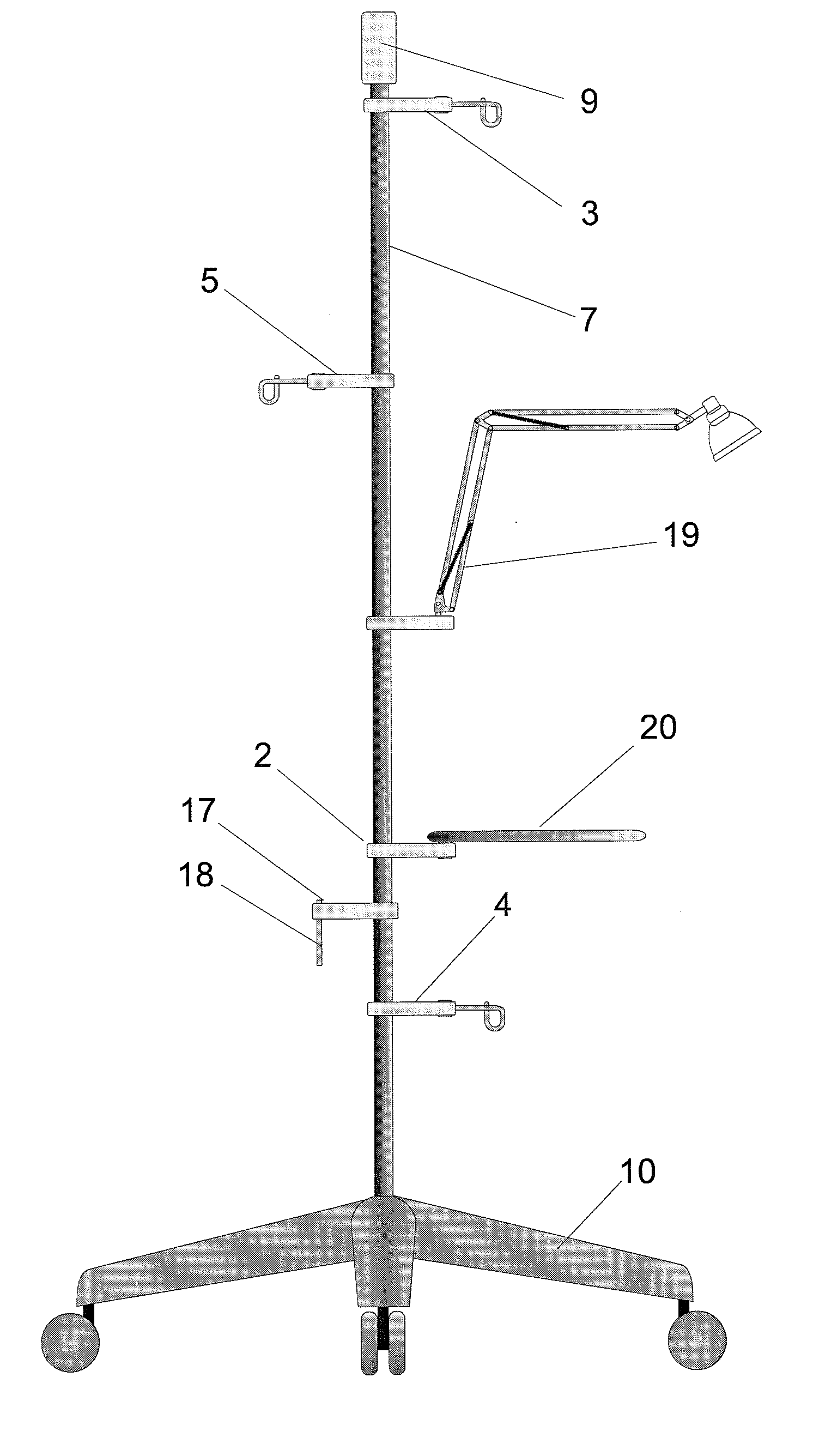
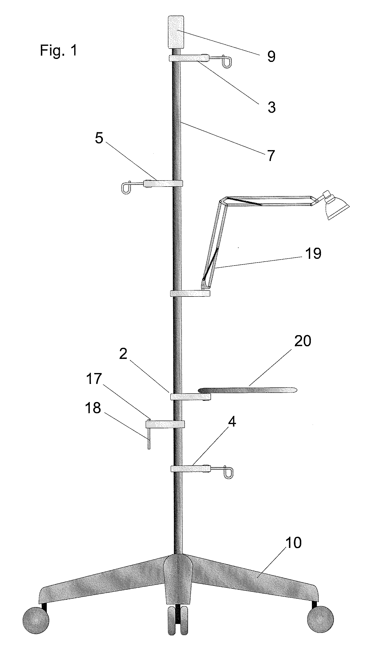
[0025]FIG. 1 shows a typically assembly in which a pole 7 is mounted vertically on a wheeled base 10. The pole is surmounted with a cap 9 which serves several purposes. It seals the end of the pole 7, if the pole is a hollow tube, to prevent entry of contamination. It can bear colour or markings that identify the user, or the intended use, or the department of an institution to which the apparatus belongs, or simply an inventory number. The cap 9 is preferably fitted tightly, to prevent easy or inadvertent removal of the modules, so that a pole can typically be outfitted with a small assortment of modules and not changed casually. However, the cap 9 is removable for adding or deleting modules.

[0026]There are two types of modules. The first type ends in a hook, suitable for hanging a reservoir of medical fluids. In FIG. 1, a module 3 of the first type is in a position suitable for hanging a bag of intravenous solution. Another module 5 is identical but oriented in a different directi...


PUM


Abstract

A bracket slides on a vertical pole and grips the pole at any position to support a multiplicity of devices at various heights and extending in various directions, such as medical devices and medical fluids. The pole may be on wheels as used in hospitals in the delivery of treatment to patients, such as IV fluids and drugs that may use pumps that are also supported on the pole.

Description

BACKGROUND OF THE INVENTION[0001]1. Field of the Invention[0002]The present invention relates to the provision of medical treatment to patients, usually in hospitals, involving fluids to be delivered intravenously, pumps for such fluids, and monitors of a patient's condition.[0003]2. Description of Related Art[0004]As technology plays an increasingly important role at the bedside in a hospital and for patients in general, the need to physically support equipment also increases. Such equipment, which will here be collectively called paraphernalia, comprises without limitation pumps, monitors, lamps, intravenous and infusion reservoirs which may be bottles or bags, and reservoirs for draining body fluids. All require physical support in proximity to a patient.[0005]The current practice is to move a portable pole to a position close to the bed. These are often referred to as I.V. poles, because solutions to be injected intravenously are the most common paraphernalia on the pole, but in...

Claims


Application Information

Patent Timeline
IPC IPC(8): A61M5/14F16M13/02
CPCA61M5/1415A61M5/1417F16M11/24A61G12/008F16M11/08F16M11/42F16M2200/027F16M11/046
Inventor SUNDERLAND, MARK
Owner SUNDERLAND MARK
Why Eureka
Try Eureka