Wind power generation system of a type provided with power storage system

a power generation system and power storage technology, applied in the direction of electric generator control, machine/engine, greenhouse gas reduction, etc., can solve the problems of unbalanced power supply and demand, unnecessary charging or discharging of batteries, and loss inside the battery, so as to reduce the loss and reduce the cost of discharging batteries

Active Publication Date: 2009-12-03
HITACHI ENG & SERVICES CO LTD
View PDF10 Cites 82 Cited by
  • Summary
  • Abstract
  • Description
  • Claims
  • Application Information

AI Technical Summary

Benefits of technology

[0017]With the present invention, an output power variation in a frequency region, which is an object for suppression, can be suppressed as well as to reduce a loss being accompanied with charging and discharging of the batteries can be reduced.

Problems solved by technology

In particular, with regard to a variation of about a few minutes to 20 minutes which is called as an intermediate cycle region, it is feared that such variation leads such as to as an expansion of power supply and demand unbalance due to shortage of adjustment capacity and to an expansion of frequency variation.
However, when the control method as disclosed in patent document 1 is employed, since a simple output target value of an average value of the power generated for mitigating the objective variation in the intermediate cycle region is used, it is feared to cause an unnecessary charging or discharging of the batteries which does not contribute to mitigate the variation in the intermediate cycle region.
A charging and discharging operation of a battery inevitably accompanies a loss inside the battery.
For this reason, since a charging and discharging which does not contribute to mitigate the variation increases a loss, it is feared that natural energy cannot be utilized effectively to its maximum.

Method used


Image

  • Wind power generation system of a type provided with power storage system
  • Wind power generation system of a type provided with power storage system
  • Wind power generation system of a type provided with power storage system

Examples


embodiment 1

[0065]A first embodiment of the present invention will be explained with reference to FIG. 1 through FIG. 17.

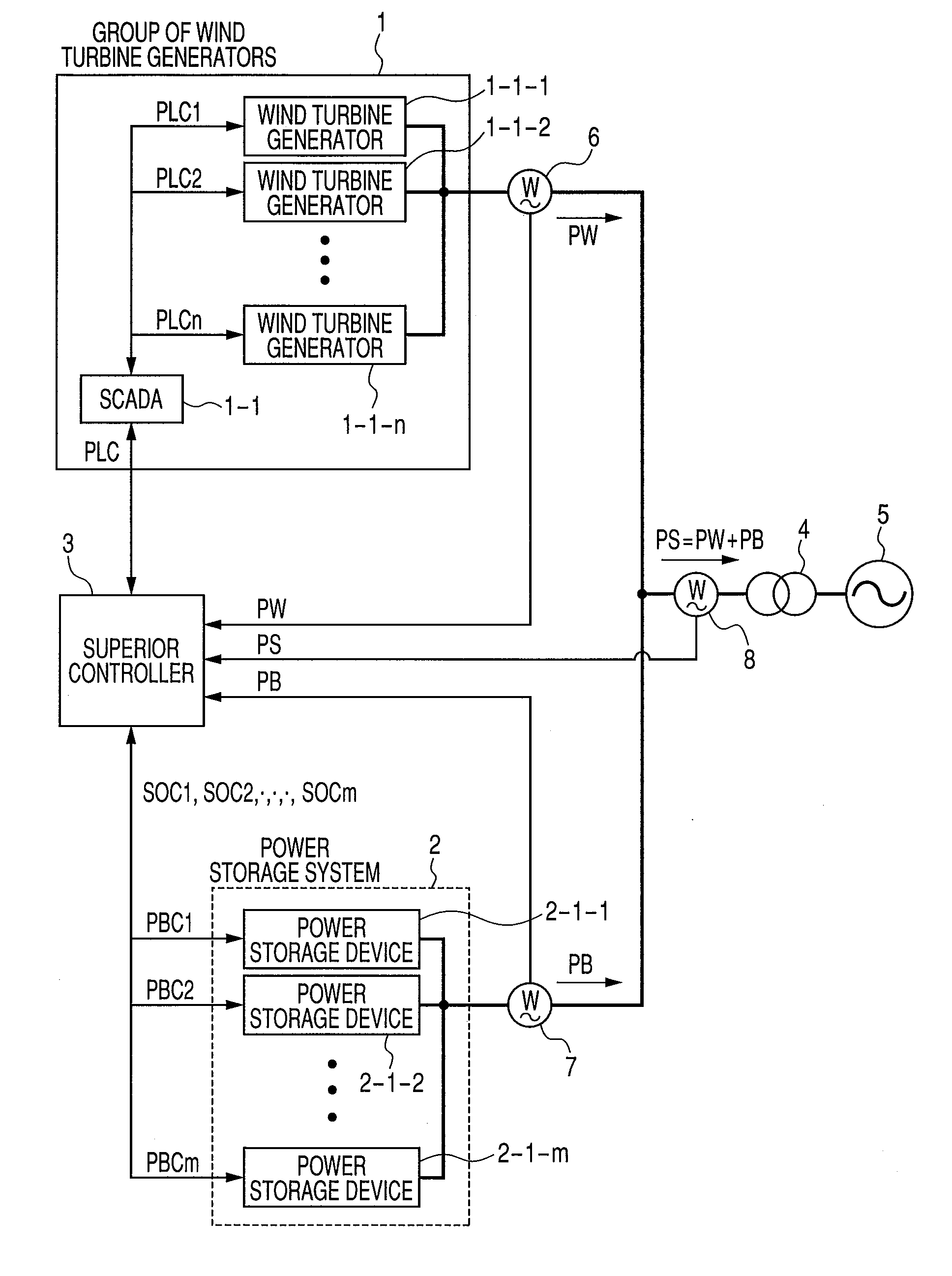
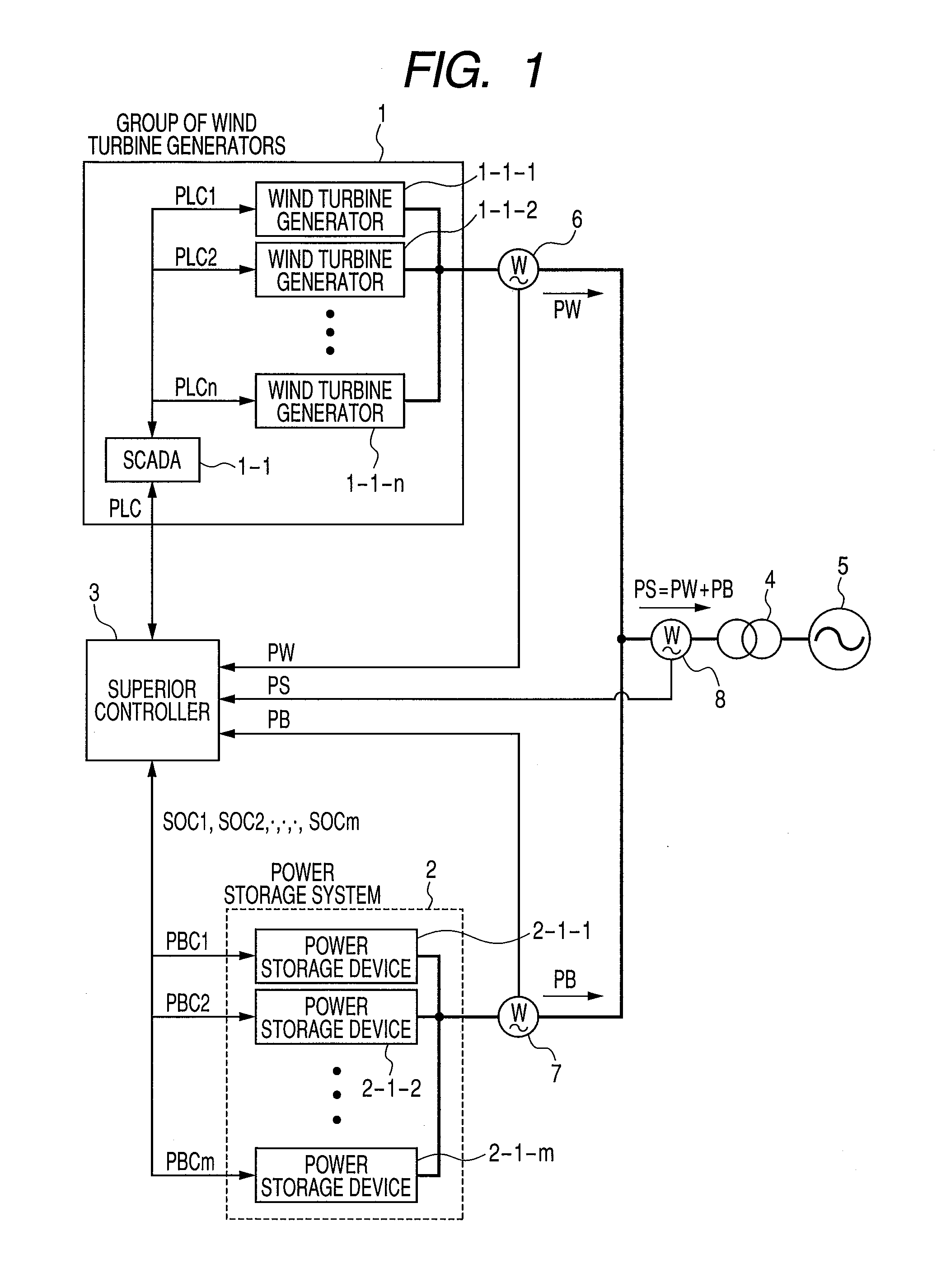
[0066]A configuration of a wind power generation system, which is an object of the present embodiment, will be explained with reference to FIG. 1. The wind power generation system of the present embodiment is configured by a group of wind turbine generators 1, a power storage system 2, a superior controller 3 and a linking transformer 4. The wind power generation system links with an electric power system 5 and the electric power generated is transmitted to the electric power system 5. At a linking point of the group of wind turbine generators, a wattmeter 6 for measuring a generation power PW of the group of wind turbine generators is disposed. Further, at a linking point of the wind power generators, a wattmeter 8 for measuring a generation power PS of the wind turbine generators is disposed. In the wind power generation system, at a linking point of the power storage syste...

embodiment 2

[0096]A second embodiment of the present invention will be explained with reference to FIGS. 18 through 20.

[0097]Differences of the present embodiment from embodiment 1 of the present invention are that the wind power generation system includes a predetermined output power upper limit command PMaxC, and the power limiting operation of the group of wind turbine generators and charging and discharging operation of the power storage system are performed in combination so that the output value of the wind power generation system is always below the output power upper limit command PMaxC. Parts different from the configuration of embodiment 1 of the present invention will be explained with reference to FIGS. 18 and 19.

[0098]A charging and discharging command computing unit 3a-3 in the present embodiment will be explained with reference to FIG. 18. Different part of the charging and discharging command computing unit 3a-3 of the present embodiment from the charging and discharging command...

embodiment 3

[0106]A third embodiment of the present invention will be explained with reference to FIGS. 21 through 27.

[0107]Differences of the present embodiment from embodiments 1 and 2 are that the wind power generation system utilizes a generation power prediction value of the group of wind turbine generators 1 based on weather forecast for the power limiting control of the group of wind turbine generators 1 and for the charging and discharging control of the power storage system 2.

[0108]A configuration of the wind power generation system of the present embodiment will be explained with reference to FIG. 21. Among the constitutional elements in the wind power generation system of the present embodiment as shown in FIG. 21, since ones bearing the same reference numerals as those in FIG. 1 are the same constitutional elements as in FIG. 1, the explanation thereof is omitted. In the wind power generation system of the present embodiment, a superior controller 3a receives a generation power pred...


PUM


Abstract

A wind power generation system having a group of wind turbine generators includes a superior controller having a generation power recording memory to record a sum of a generation power of the group of wind turbine generators and a charge and discharge power of a power storage system, a charge and discharge power command computing device for computing a charge and discharge power command for the power storage system in a second period by making use of information of the output power in a first period computed in the output power computing unit and information of a detection value at the present of the generation power recording memory, and a charge and discharge power control device.

Description

BACKGROUND OF THE INVENTION[0001]1. Field of the Invention[0002]The present invention relates to a wind power generation system provided with a power storage system and a windmill power generation system.[0003]2. Description of the Related Art[0004]As a measure of converting naturally occurring renewable energy into electric power energy, a group of wind turbine generators is utilized.[0005]Since an energy source for the group of wind turbine generators is temporally varying wind energy, the power generated by the group of wind turbine generators also varies temporally.[0006]In an electric power system, a power generated by a large scaled power generator is adjusted depending on the magnitude of a power demand and a balance of the power supply and demand is maintained. For this reason, when many groups of wind turbine generators which are power sources with large variation are linked to an electric power system as disclosed in non-patent document 1, it is concerned about a shortage ...

Claims


Application Information

Patent Timeline
Patent Type & Authority Applications(United States)
IPC IPC(8): H02P9/04
CPCF03D7/028F03D7/048F03D9/021Y02E10/725F05B2210/18Y02E10/723F05B2210/16F03D9/11H02J3/32H02J7/34Y02E70/30F03D9/257H02J2300/28H02J3/381Y02E10/76Y02E10/72
Inventor OOHARA, SHINYAHOSHINO, NAOKIIWATA, TAKESHI
Owner HITACHI ENG & SERVICES CO LTD
Why Eureka
Try Eureka