
Illuminative light communication device and lighting device

a technology of illumination light and communication device, which is applied in the direction of powerline communication application, identification means, instruments, etc., can solve the problem that communication cannot be carried out through conventional illumination light communication without lighting

Inactive Publication Date: 2009-12-03
NAKAGAWA LAB INC
View PDF4 Cites 67 Cited by
  • Summary
  • Abstract
  • Description
  • Claims
  • Application Information

AI Technical Summary

Benefits of technology

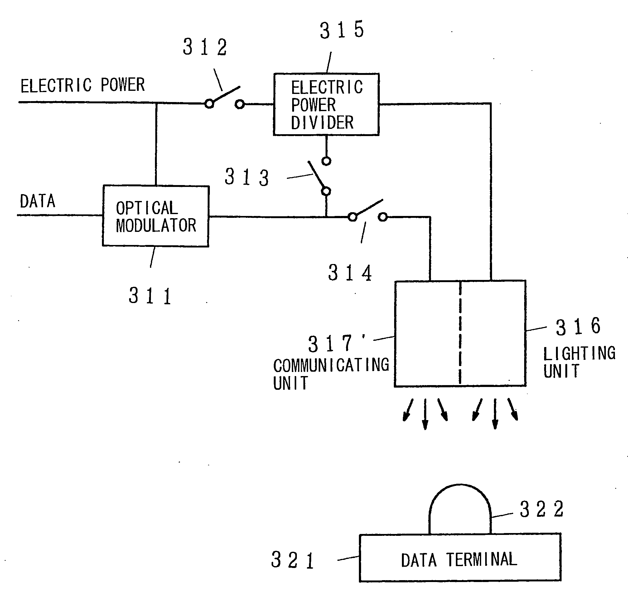
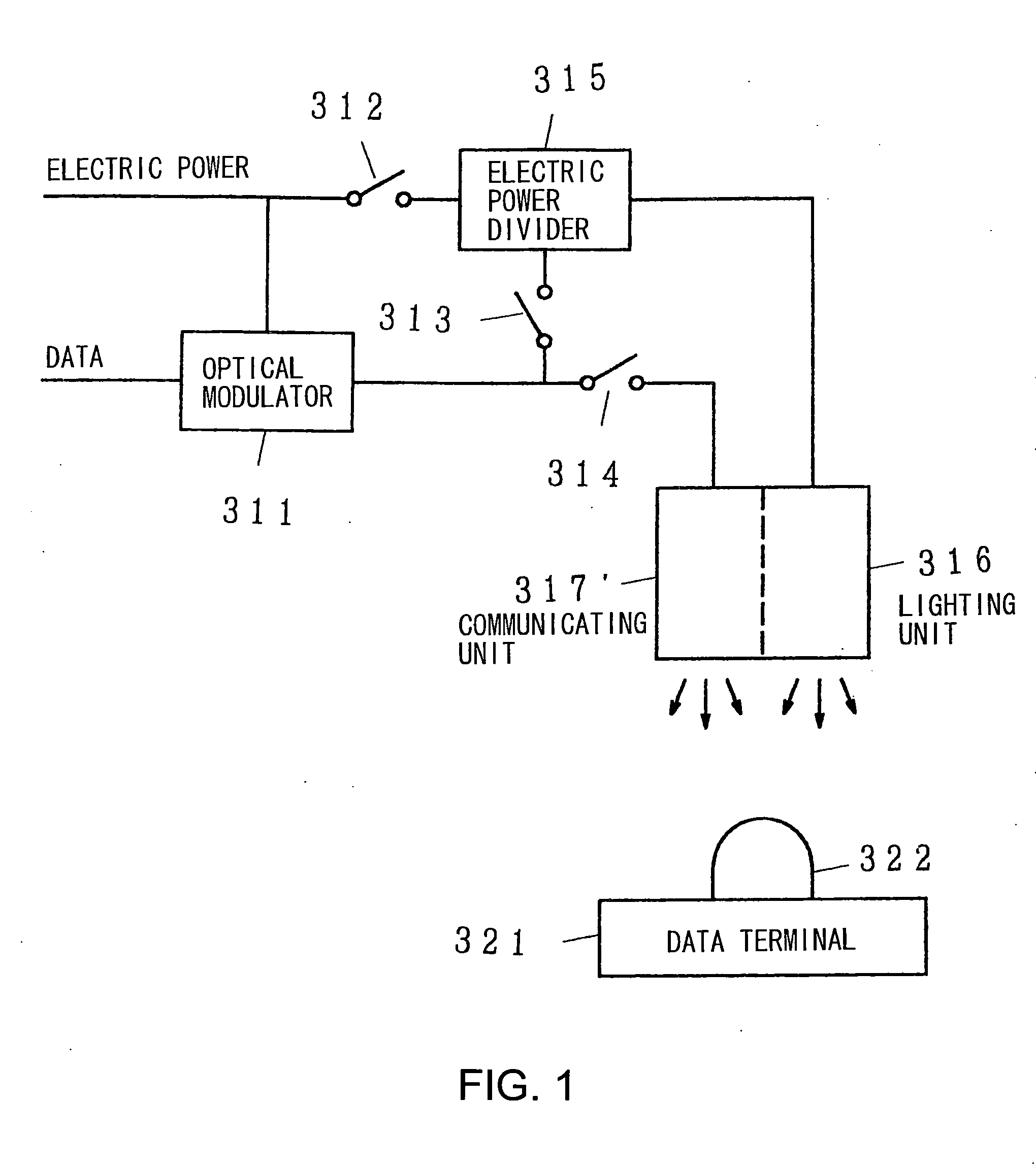
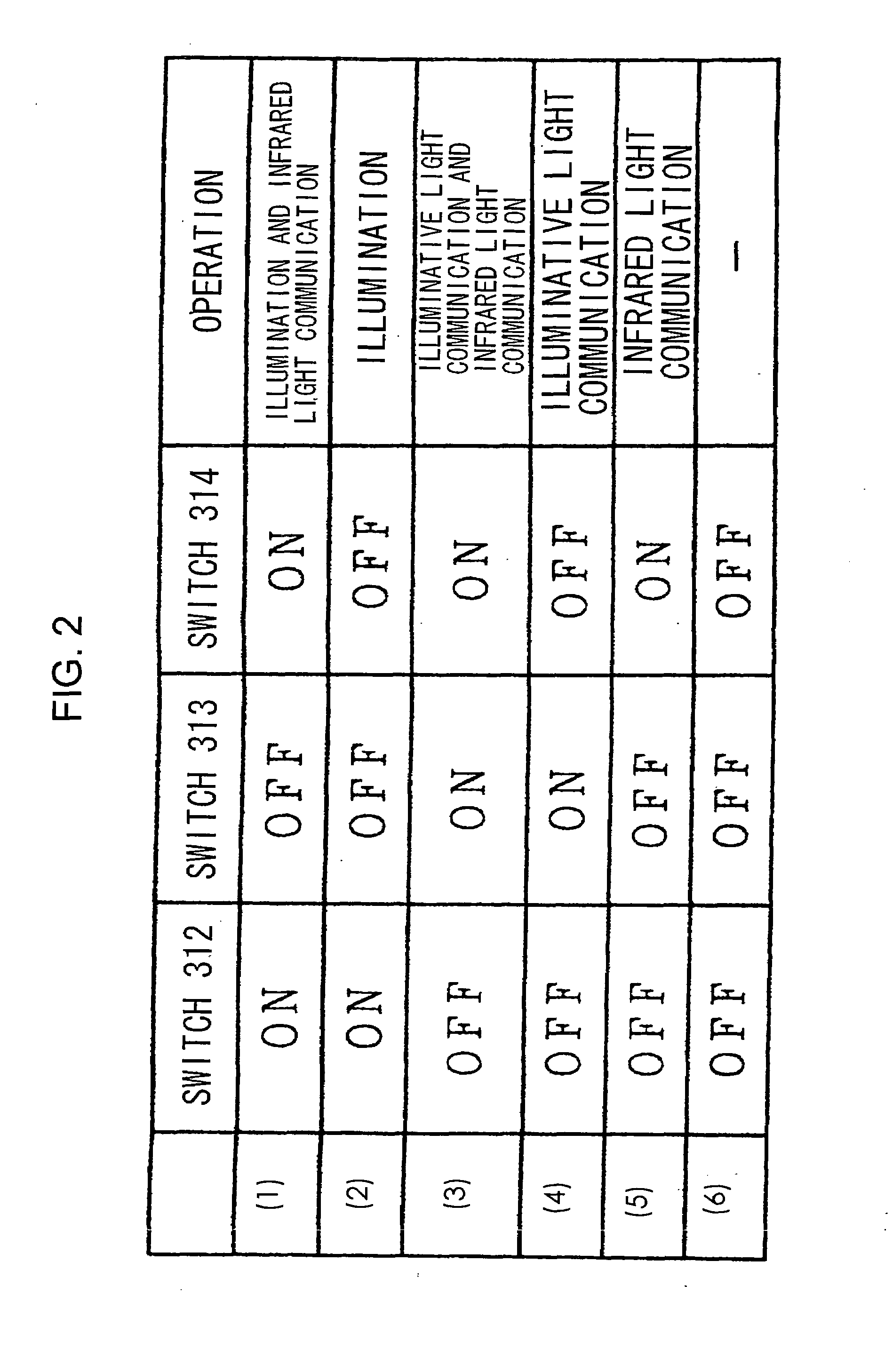
[0006]An illuminative light communication device includes a lighting unit that emits light for lighting and a modulator that controls blinking or light intensity of the lighting unit in accordance with data, thereby modulating the emitted light. In response to an on-switching instruction, the modulator modulates in accordance with the data while supplying sufficient electric power for lighting to the lighting unit while in response to an off-switching instruction, the modulator modulates in accordance with the data to allow the lighting unit to blink a number of times necessary for communication.

Problems solved by technology

As a result, communication is possible even without lighting, although communication could not be carried out through conventional illuminative light communication without lighting.

Method used


Image

  • Illuminative light communication device and lighting device
  • Illuminative light communication device and lighting device
  • Illuminative light communication device and lighting device

Examples


Embodiment Construction

[0018]FIG. 8 is a diagram of a configuration of an exemplary typical white LED. In the drawing, 331 and 341 denote LED devices, 332 denotes a red light emitting element, 333 denotes a green light emitting element, 334 denotes a blue light emitting element, 342 denotes a light emitting element, and 343 denotes fluorescer. An exemplary white LED shown in FIG. 8A is configured such that the red light emitting element 332, the green light emitting element 333, and the blue light emitting element 334 are arranged in the LED device 331. White light can be seen when red, green, and blue light emitted from respective light emitting elements are mixed.

[0019]In the case of an exemplary white LED shown in FIG. 8B, a blue or an ultraviolet light emitting element 342 is provided in the LED device 341, and the fluorescer 343 is provided surrounding the light emitting element 342. As with a fluorescent lamp, the LED device 341 has the fluorescer 343, which emits white light when blue light or ultr...


PUM


Abstract

In the case of performing communication by using illumination light when the illumination is on, switches are turned on, a signal modulated in an optical modulation part in accordance with information is superposed to a power waveform for the illumination with a power distributor and the illumination 16 is driven in a modulated state. When the illumination is off, the switches are turned off, a switch is turned on and a communication part is driven in a modulated state by the optical modulation part. The communication part can be constituted so as to include an infrared light emitting element part to perform infrared communication when the illumination is off. Consequently communication can be performed not only when the of illumination is on but also when the lighting is kept off. The communication device can be constituted of one element integrating the illumination part and the communication part, so that a compact system can be constituted.

Description

CROSS-REFERENCES TO RELATED APPLICATIONS[0001]This application is a continuation of U.S. patent application Ser. No. 10 / 532,250 filed Oct. 23, 2003, as International Application No. PCT / JP03 / 013539, now pending, the contents of which, including specification, claims and drawings, are incorporated herein by reference in their entirety. This application claims priority from Japanese Patent Application Serial No. 2003-070673 filed Mar. 14, 2003, the contents of which are incorporated herein by reference in their entireties.BACKGROUND OF THE INVENTION[0002]The present invention aims to provide an illuminative light communication device, which allows communication even without lighting and effectively utilizes infrared light data communication, and a lighting device preferable for such illuminative light communication device.[0003]According to such objective, the illuminative light communication device includes a lighting unit that emits light for lighting, a modulator that controls blin...

Claims


Application Information

Patent Timeline
Patent Type & Authority Applications(United States)
IPC IPC(8): H04B10/04G09F9/33H04B3/54H04B10/114H04B10/116
CPCF21Y2101/02G09F9/33H01L2924/3025F21K9/10F21V33/0052H01L2224/48247H01L2224/48091H01L25/0753H04B3/54H04B10/1141H04B10/1149H04B10/116H04B2203/5412H04B2203/5458H05B37/0263H05B37/0272Y02B20/72H01L2924/00014H01L2924/00F21K9/20F21Y2115/10F21K9/65H05B47/185H05B47/195H05B47/1965F21S8/08G08B27/00
Inventor NAKAGAWA, MASAOKOMINE, TOSHIHIKOHARUYAMA, SHINICHIRO
Owner NAKAGAWA LAB INC
Learn More