Solar-power collector

a solar power collector and solar energy technology, applied in solar heat systems, pv power plants, light and heating equipment, etc., can solve the problems of requiring a large space and dimension to collect enough solar power, affecting the efficiency of solar energy collection, so as to avoid overheating problems

Inactive Publication Date: 2009-08-20
GENIUS ELECTRONICS OPTICAL CO LTD
View PDF3 Cites 13 Cited by
  • Summary
  • Abstract
  • Description
  • Claims
  • Application Information

AI Technical Summary

Benefits of technology

[0004]This invention proposes a solar-power collector that can double collect solar power under same total solar panel size as traditional apparatus. Accordingly, it can generate sufficient electrical power without requiring solar panel of big dimension, can be produced at lower unit cost, can be spread out more easily to regular households, and it has also the feature of long life.
[0007]Two or more layers of solar panel modules—they are placed beneath the light deflector. Each solar panel module is composed of multiple solar panels that scatter around, and the solar panels of upper and lower layers are intercross placed. With so, sunlight can focus and disperse through the convexes and concaves of the light deflector, and the upper layer of solar panel module absorbs the dispersed sunlight while the lower layer module, through the gaps between panels of upper layer module, absorbs the after-focus dispersed sunlight. This is designed so to fully absorb sunlight and avoid overheating problem when sunlight just focuses on certain points on solar panels.

Problems solved by technology

Aforementioned two methods can both achieve to turn solar power into electricity, but they require big space and dimension to collect sufficient solar power.
Unfortunately, the bigger size the apparatus is, the costly it will be.
Although the light-directing and reflective devices can greatly have sunlight focused on the solar panel, it indeed also has following drawbacks: (1) Although the its solar panels are properly spaced to save manufacturing costs, it encounters the loss of some sunlight and may at some certain times fail to direct lights focused onto the solar panel due to the displacement of sunlight, thus causing low collecting efficiency.
(2) Like other regular solar-power collectors, such equipment also requires the wide placement of solar panels when in condition of unable to fully absorb sunlight, causing high implementing costs and thus hard to get popular.

Method used


Image

  • Solar-power collector
  • Solar-power collector
  • Solar-power collector

Examples


Embodiment Construction

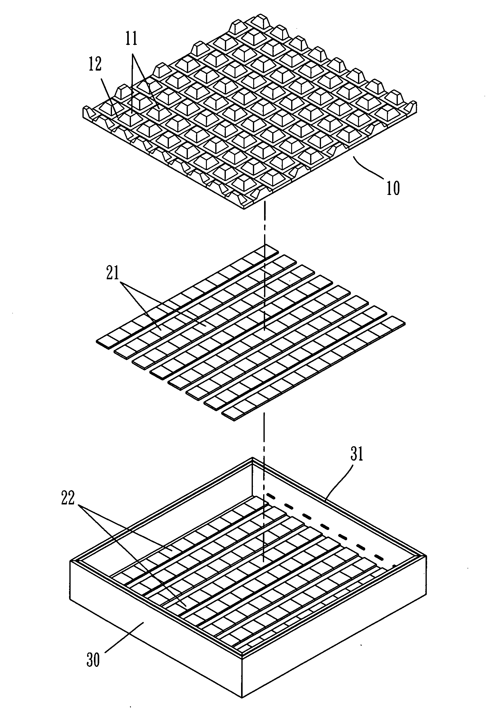
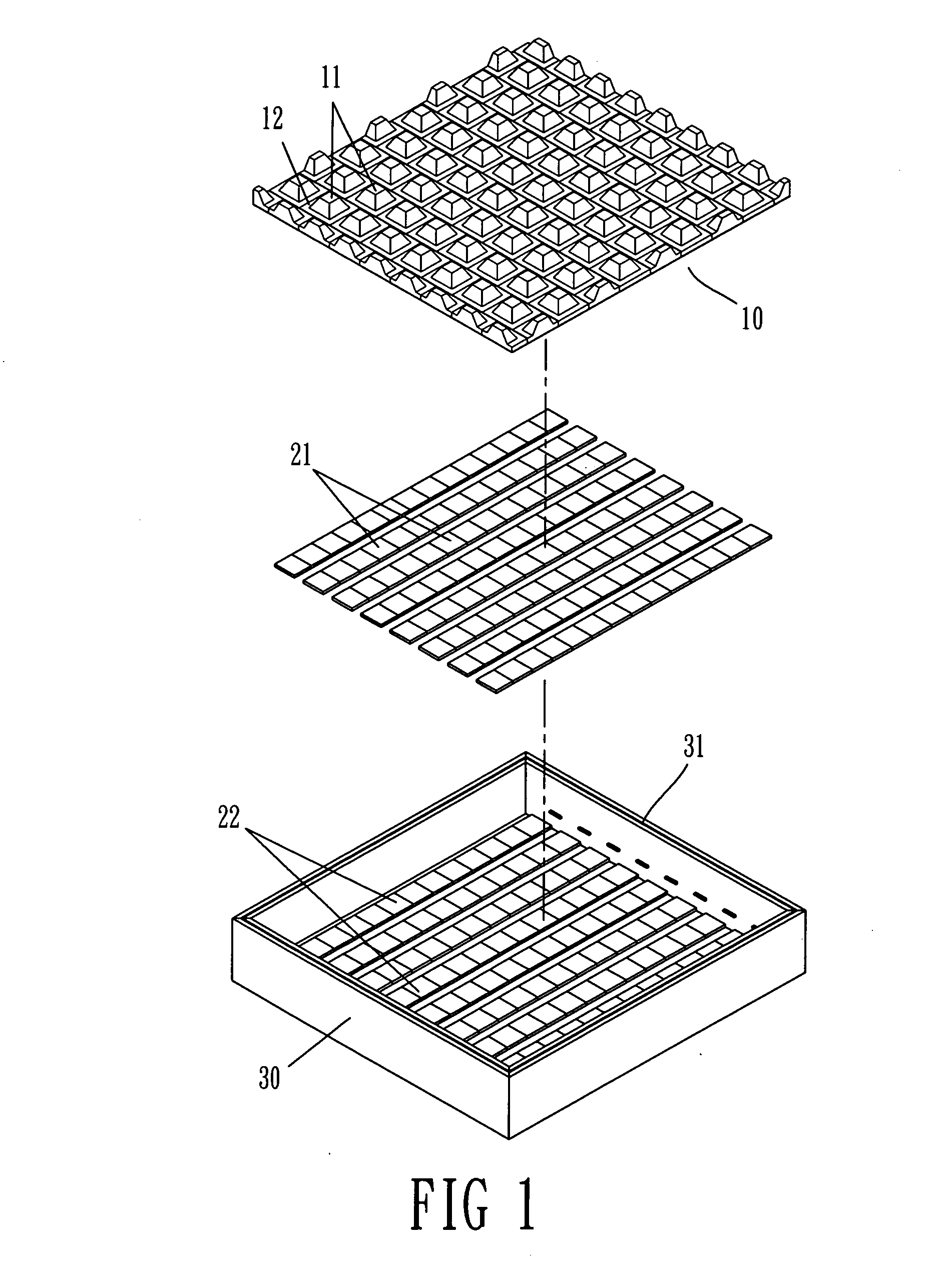
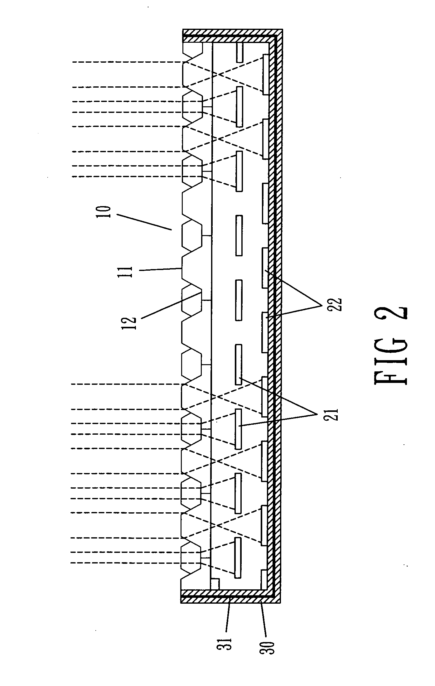
[0016]Further, please be described of a preferred embodiment as below. First referring to FIG. 1 and 2, the invention comprises: a transparent light deflector 10, and at least upper and lower layers of solar panel modules 21, 22 below the light deflector 10.

[0017]The transparent light deflector 10 has multiple convexes 11 and concaves 12 on either its top of bottom surface. The convexes 11 can be either round-shaped, cone-shaped, pyramid-, awl-shaped, or trapezoid column-shaped. The concaves 12 can be not only on top surface but also on bottom surface at the corresponding positions to the convexes 11 as shown in FIG. 3. The arrangement of the convexes 11 can be in either 2-D crisscross or random alignments, thus looks continuous or intercross wave-shape, triangle-shape or trapezoid-shape in its sectional view.

[0018]The two layers of solar panel modules 21, 22 placed beneath the light deflector. Each solar panel module is composed of multiple solar panels in 2-D alignments, and the s...


PUM


Abstract

This invention proposes one kind of solar-power collecting apparatus that utilizes different lens structure and double layers of solar panel modules to optimize the absorption of solar power within a limited space, and better protect the life of solar panels by avoiding overheats generated from overly focused sunlight.

Description

BACKGROUND OF THE INVENTION[0001]This invention is regarding to a technique that can optimize the absorption of solar power within a limited space, and prolong the life of solar panels.[0002]Current solar power collecting techniques generally come from two methods by principles: (1) utilize and achieve through heat chamber. (2) utilize reflection mirrors or lens to focus sunlight on the surfaces of solar panels for them to absorb. Aforementioned two methods can both achieve to turn solar power into electricity, but they require big space and dimension to collect sufficient solar power. Unfortunately, the bigger size the apparatus is, the costly it will be. In Taiwan Patent Publication Number: M3 18670 “Refraction-based solar power collector”, for example, it comprises: a light-directing device, a transparent body with continuous pyramid-structured, a reflective device used to reflect the light refracted from the light-directing device and a solar panel. The light-directing device, r...

Claims


Application Information

Patent Timeline
Patent Type & Authority Applications(United States)
IPC IPC(8): H01L31/052F24S23/71
CPCF24J2/06H01L31/0543Y02E10/52F24J2/08F24S23/00F24S23/30
Inventor CHANG, KUO-WEN
Owner GENIUS ELECTRONICS OPTICAL CO LTD
Why Eureka
Try Eureka