Controller for drive system

a technology of controller and drive system, which is applied in the direction of motor/generator/converter stopper, engine-driven generator propulsion, record information storage, etc., can solve the problems of not always being able to obtain voltage, not always being able to obtain regenerative electric power, and not always being able to store sufficient electric power

Inactive Publication Date: 2007-07-10
TOYOTA JIDOSHA KK
View PDF6 Cites 13 Cited by
  • Summary
  • Abstract
  • Description
  • Claims
  • Application Information

AI Technical Summary

Benefits of technology

[0011]According to the present invention, if the value of electric power to be stored in the power storage mechanism is larger than the value of electric power to be generated by the second rotating electric machine under regenerative braking of the vehicle, the engine is driven to allow the first rotating electric machine to generate electric power to be stored in the power storage mechanism. Accordingly, if the power storage mechanism cannot be fully charged, under regenerative braking, with electric power (regenerative electric power) generated by the second rotating electric machine, the power storage mechanism can further be charged with the electric power generated by the first rotating electric machine. It is therefore possible to supply sufficient electric power from the power storage mechanism to at least one of the first rotating electric machine and the second rotating electric machine under reacceleration after braking to generate driving force for accelerating the vehicle. As a result, it is possible to provide a controller for a drive system, the controller allowing sufficient electric power required to accelerate the vehicle to be stored under braking.
[0013]According to the present invention, when the value of electric power to be stored in the capacitor is larger than the value of electric power to be generated by the second rotating electric machine under regenerative braking of the vehicle, the engine is driven to allow the first rotating electric machine to generate the electric power to be stored in the capacitor. Accordingly, if the capacitor cannot be fully charged, under regenerative braking, with electric power (regenerative electric power) generated by the second rotating electric machine, the capacitor can further be charged with the electric power generated by the first rotating electric machine. It is therefore possible to supply sufficient electric power from the capacitor to at least one of the first rotating electric machine and the second rotating electric machine under reacceleration after braking to generate driving force for accelerating the vehicle.
[0015]According to the present invention, when the value of electric power to be stored in the capacitor is smaller than the value of electric power to be generated by the second rotating electric machine under regenerative braking of the vehicle, electric power generated by the second rotating electric machine is stored in the capacitor and the battery. It is therefore possible to store surplus power, which cannot be stored in the capacitor alone, in the battery.

Problems solved by technology

However, under regenerative braking, it is not always possible to obtain voltage that reaches or exceeds a permissible value between the terminals of the capacitor.
In other words, it is not always possible to obtain regenerative electric power with which the capacitor is fully charged.
In such a case, it may not be possible to store sufficient electric power required to accelerate a vehicle as demanded by a driver under reacceleration after regenerative braking.

Method used


Image

  • Controller for drive system
  • Controller for drive system
  • Controller for drive system

Examples


Embodiment Construction

[0022]The embodiment of the present invention will hereinafter be described in detail with reference to the drawings. In the following description, the same parts are denoted by the same reference characters, and have the same names and functions. Therefore the detailed description thereof will not be repeated.

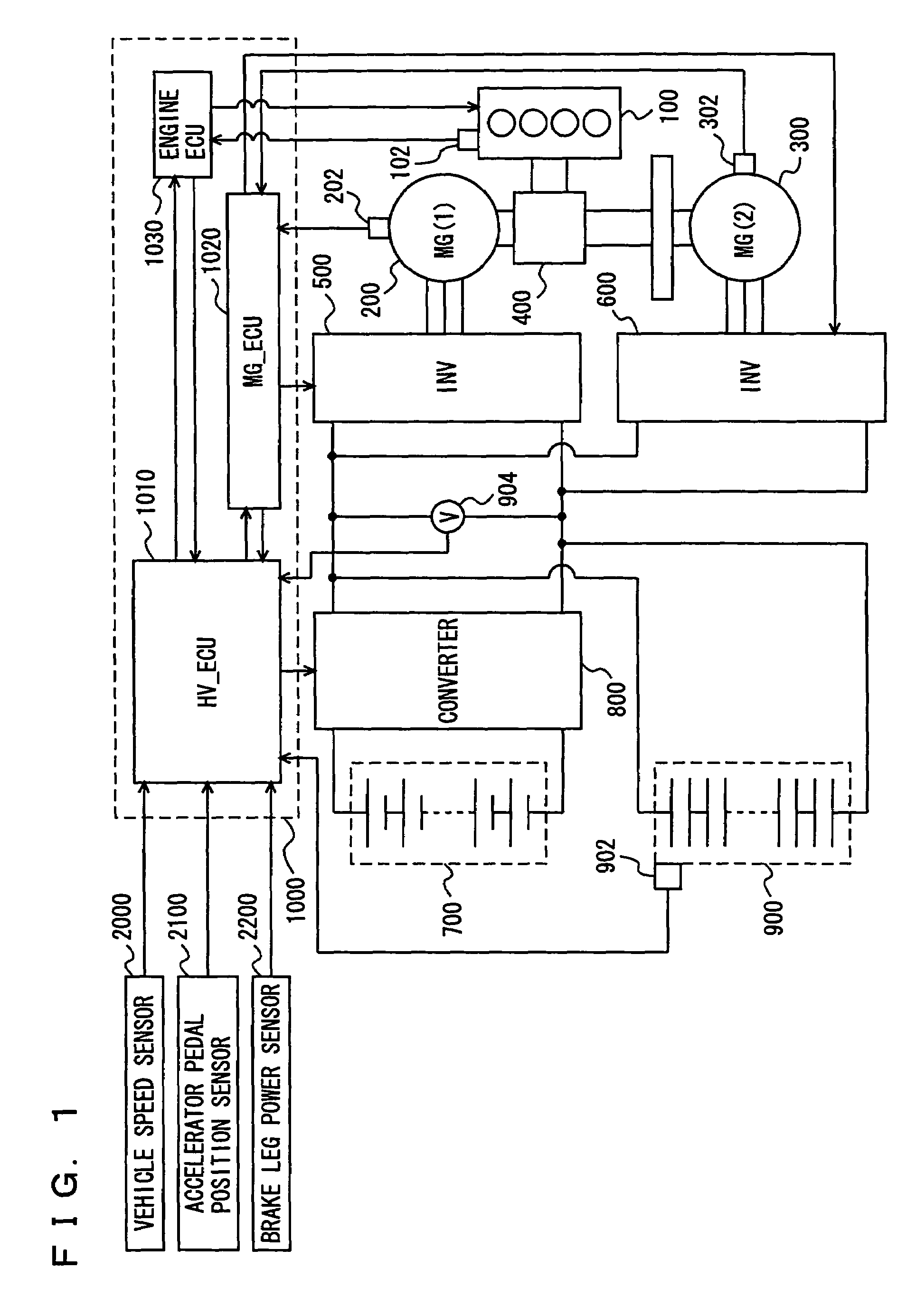
[0023]Referring to FIG. 1, there will be described a hybrid vehicle having a controller according to the present embodiment mounted thereon. The vehicle includes an engine 100, a Motor Generator (MG) (1) 200, an MG (2) 300, a power split device 400, an inverter (1) 500, an inverter (2) 600, a battery 700, a converter 800, and a capacitor 900. The vehicle runs by driving force obtained from at least one of engine 100 and MG (2) 300.

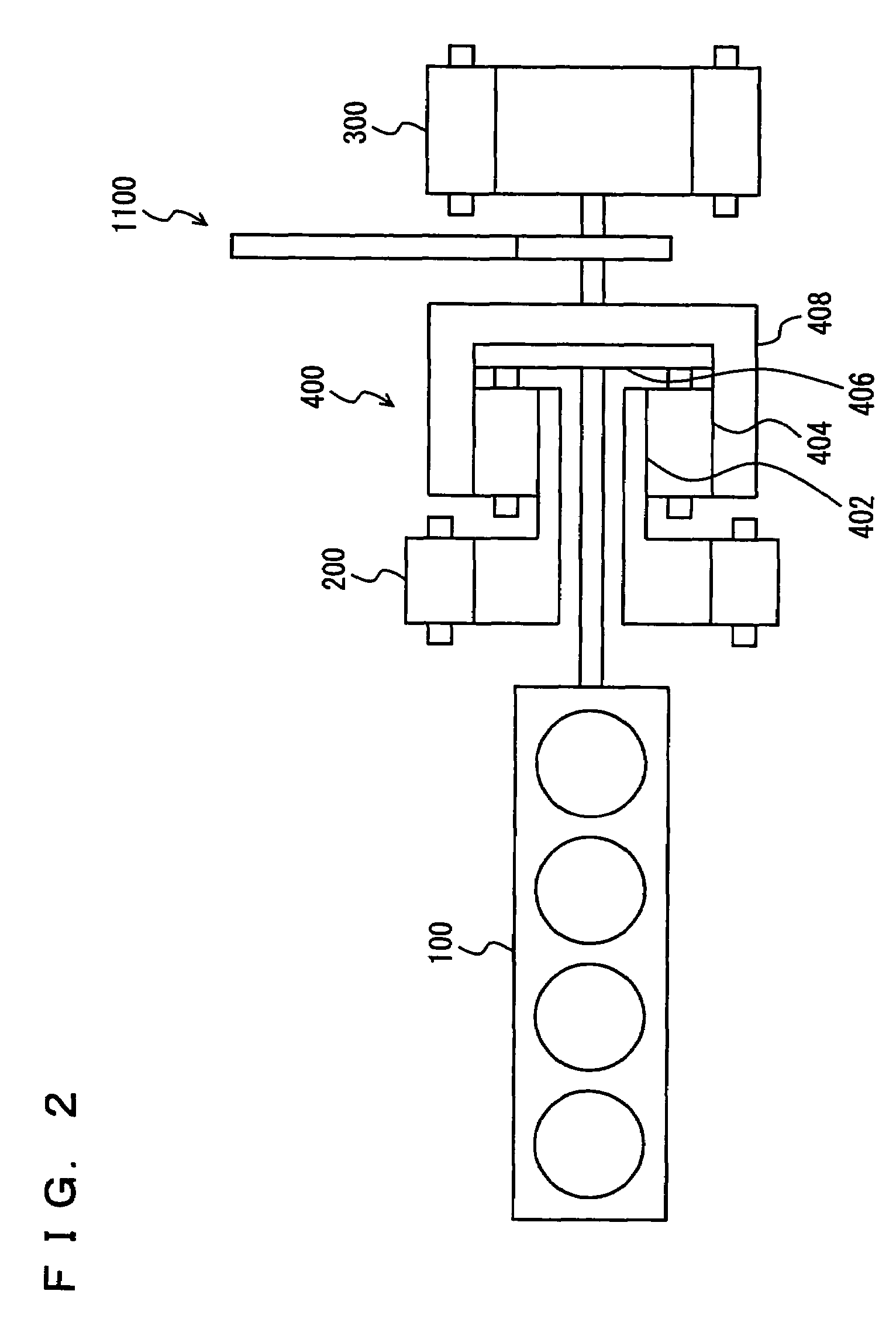
[0024]Engine 100, MG (1) 200, and MG (2) 300 are connected via power split device 400. Motive power generated by engine 100 is divided by power split device 400 into two paths. One of the paths is a path for driving wheels (not shown) through a reduc...


PUM


Abstract

An ECU executes a program including the steps of calculating a capacitor charging electric power value W (1) (a value of electric power to be stored in a capacitor) based on a voltage value of the capacitor, if a vehicle is under braking, calculating a regenerative electric power value W (2) (a value of electric power to be generated by an MG (2) under regenerative braking), if the capacitor charging electric power value W (1) is larger than the regenerative electric power value W (2), driving an engine, generating electric power by MG (1) by driving force of the engine, and charging the capacitor with the electric power generated by the MG (1) and the MG (2).

Description

[0001]This nonprovisional application is based on Japanese Patent Application No. 2005-135248 filed with the Japan Patent Office on May 6, 2005 , the entire contents of which are hereby incorporated by reference.BACKGROUND OF THE INVENTION[0002]1. Field of the Invention[0003]The present invention relates to a controller for a drive system, and in particular to a technique of storing electric power generated under regenerative braking of a vehicle.[0004]2. Description of the Background Art[0005]In recent years, as part of measures to address environmental problems, a hybrid vehicle that runs by driving force obtained from at least one of an engine and a motor has received attention. A battery, a capacitor (condenser), and the like are mounted on such a hybrid vehicle for storing electric power to be supplied to the motor.[0006]Japanese Patent Laying-Open No. 08-296537 discloses a retarder device that charges a capacitor and a battery with electric power regenerated under braking. The...

Claims


Application Information

Patent Timeline
Patent Type & Authority Patents(United States)
IPC IPC(8): H02P1/00H02P3/00H02P5/00B60K6/365B60K6/445B60K6/543B60L7/22B60W10/08B60W10/26B60W20/00
CPCB60K6/365B60K6/445B60L7/16B60L7/20B60L11/005B60W10/08B60W10/26B60L11/123B60L11/14B60L11/1853B60L11/1868B60W20/00Y02T10/7022B60L2210/10B60L2210/30B60L2210/40B60L2240/12B60L2240/545B60L2240/547B60L2240/549Y02T10/7077Y02T10/7005Y02T10/7241Y02T10/7066Y02T10/7216Y02T10/6217Y02T10/6239B60L50/40B60L50/61B60L50/16B60L58/18B60L58/20Y02T10/62Y02T10/70Y02T10/72Y02T10/7072B60W20/13
Inventor ISHIKAWA, TETSUHIROYOSHIDA, HIROSHI
Owner TOYOTA JIDOSHA KK
Why Eureka
Try Eureka