Device for supplying power to field devices

a field device and thermoelectric converter technology, applied in the direction of thermoelectric devices with peltier/seeback effect, electromagnetic wave systems, electric devices, etc., can solve the problems of inability to use standardized field devices, high design complexity of the arrangement of the thermoelectric converter in this device, and the inability to reduce the heat loss of the pipeline carrying process media, so as to minimize the heat loss caused by mounting the thermoelectric converter on the pipeline, and optimize the effect of heat transfer

Inactive Publication Date: 2007-10-04
ABB (SCHWEIZ) AG
View PDF3 Cites 13 Cited by
  • Summary
  • Abstract
  • Description
  • Claims
  • Application Information

AI Technical Summary

Benefits of technology

[0007] An exemplary arrangement accommodates the thermoelectric converter in a separate enclosure from the field device, where the electrical power generated in the thermoelectric converter can be transferred to the field device by means of electrical wires or wireless transmission. This physical separation of the thermoelectric converter from the field device means that the field device can be arranged without physical constraints. In addition, this separation has the advantage that standardized field devices can be used. Furthermore, in such an exemplary arrangement there is no need to tap into the pipeline carrying process media, thereby avoiding the disadvantages cited for document DE 201 07 112 U1. In this arrangement, the thermoelectric converter can also be arranged in a simple manner on the pipeline, because the holder of the thermoelectric converter does not need to carry the weight of the field device as well. In addition, there is the possibility of integrating most of the thermoelectric converter in an existing insulation for the pipeline. The heat losses caused by mounting the thermoelectric converter on the pipeline can thereby be minimized. The heat lost from the pipeline carrying process media can thus be reduced virtually to the amount of heat that can be used for the electrical power conversion for the field device.
[0008] Physically separating the thermoelectric converter from the field device also delivers particular advantages when maintaining and repairing the field device. For example, the field device can be arranged simply and reversibly in the process plant. Should the field device need servicing, it can be removed without major effort because the thermal coupling required for power generation only takes place with the thermoelectric converter. The field device can also be provided at a secure location in the process plant where it is protected against potential fault situations.
[0009] In an exemplary embodiment, a thermoelectric converter is arranged adjacent to the field device on a pipeline carrying process media, where the thermoelectric converter has converter sides oriented towards the process and away from the process respectively, which form the two required points having different temperatures. Thus the actual thermoelectric converter having its converter sides oriented towards the process and away from the process respectively can constitute part of the enclosure. In addition, optimum heat transfer from the pipeline carrying process media to the thermoelectric converter is thereby possible. Advantageously, thermal conduction materials, in particular a heat transfer compound, can also be provided between the pipeline carrying process media and the converter side oriented towards the process, which can be used to optimize heat transfer. In addition, the thermoelectric converter can be provided on the converter side oriented away from the process with a heat sink having a large surface area to the surroundings. A predefined path for the heat flow in the thermoelectric converter can be created by the provided heatsink. In order that the heatsink affords good heat transfer to the surroundings of the thermoelectric converter, it can project at least partially or even completely out of the enclosure of the thermoelectric converter. This enables good heat dissipation to the surroundings of the thermoelectric converter, whereby the required temperature difference between the two points, i.e. converter sides, essential to operation can be maintained. In other words, a temperature transfer or equalization from the converter side oriented towards the process to the converter side oriented away from the process is avoided. It is thus assured that the thermoelectric converter can generate sufficient electrical power for the field device, by means of the existing temperature difference.
[0013] In another exemplary embodiment of the arrangement, the field device comprises an energy storage device, in particular a battery, a storage capacitor or the like. In addition, an energy management system can be provided for the field device, where the energy management system can be integrated in a controller, or a control, data-acquisition and / or processing module. The total energy consumption of the field device can be minimized using the energy management system. The energy management system can also be connected to the central data-processing device via the wireless communications interface. If it is established, for example, that the pipeline carrying process media is not currently conveying any process medium, the power consumption of the field device can be reduced via the central data-processing device by setting the field device to a “stand-by” state until the process medium is again being conveyed through the pipeline. Possible fluctuations in power from the thermoelectric converter can be smoothed out by the optional use of the energy storage device. Depending on the size of the energy storage device, the field device can thus also be run temporarily without power from the thermoelectric converter.

Problems solved by technology

In such an arrangement, however, there is the problem that the first sensing point of the thermoelectric converter, which projects into the process medium, needs to be specially protected against corrosion and contamination, which over time could impair the heat transfer from the medium to the sensor point, in particular, and hence the efficiency of the thermoelectric converter.
In addition, the particular arrangement of the thermoelectric converter in this device involves a high level of design complexity.
In addition, standardized field devices cannot be used because the additional thermoelectric converter is arranged in the field device.

Method used


Image

  • Device for supplying power to field devices
  • Device for supplying power to field devices
  • Device for supplying power to field devices

Examples


Embodiment Construction

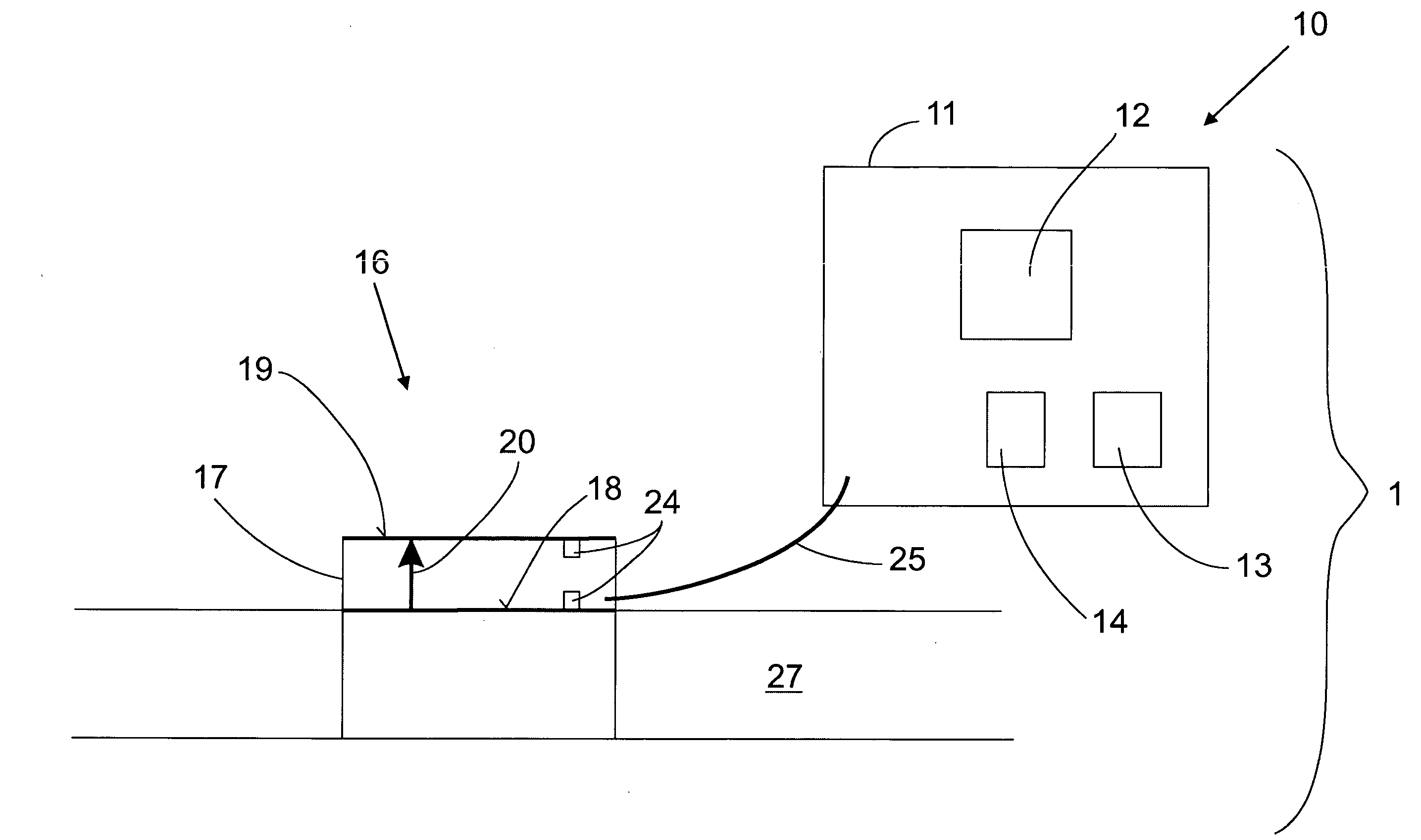
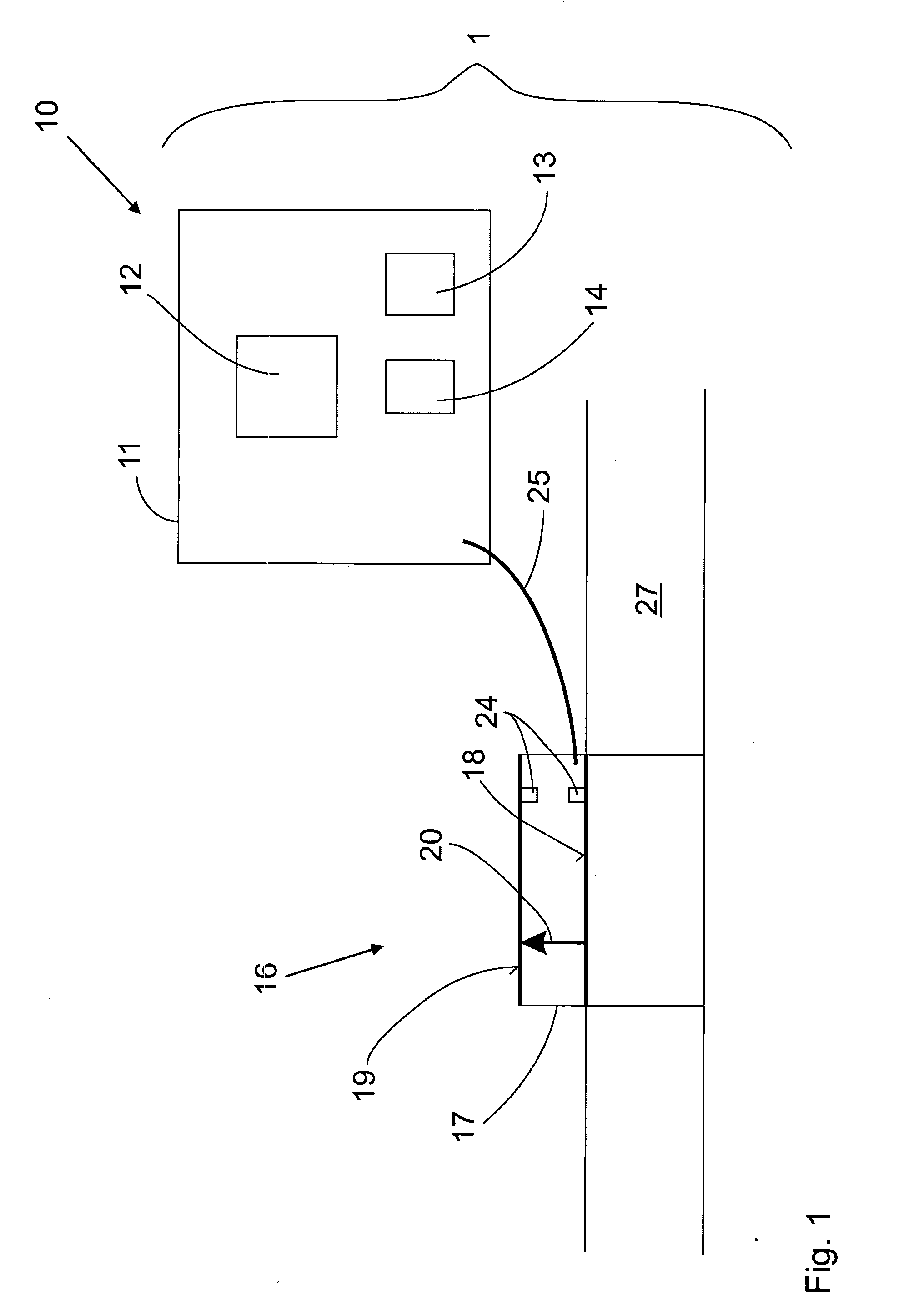
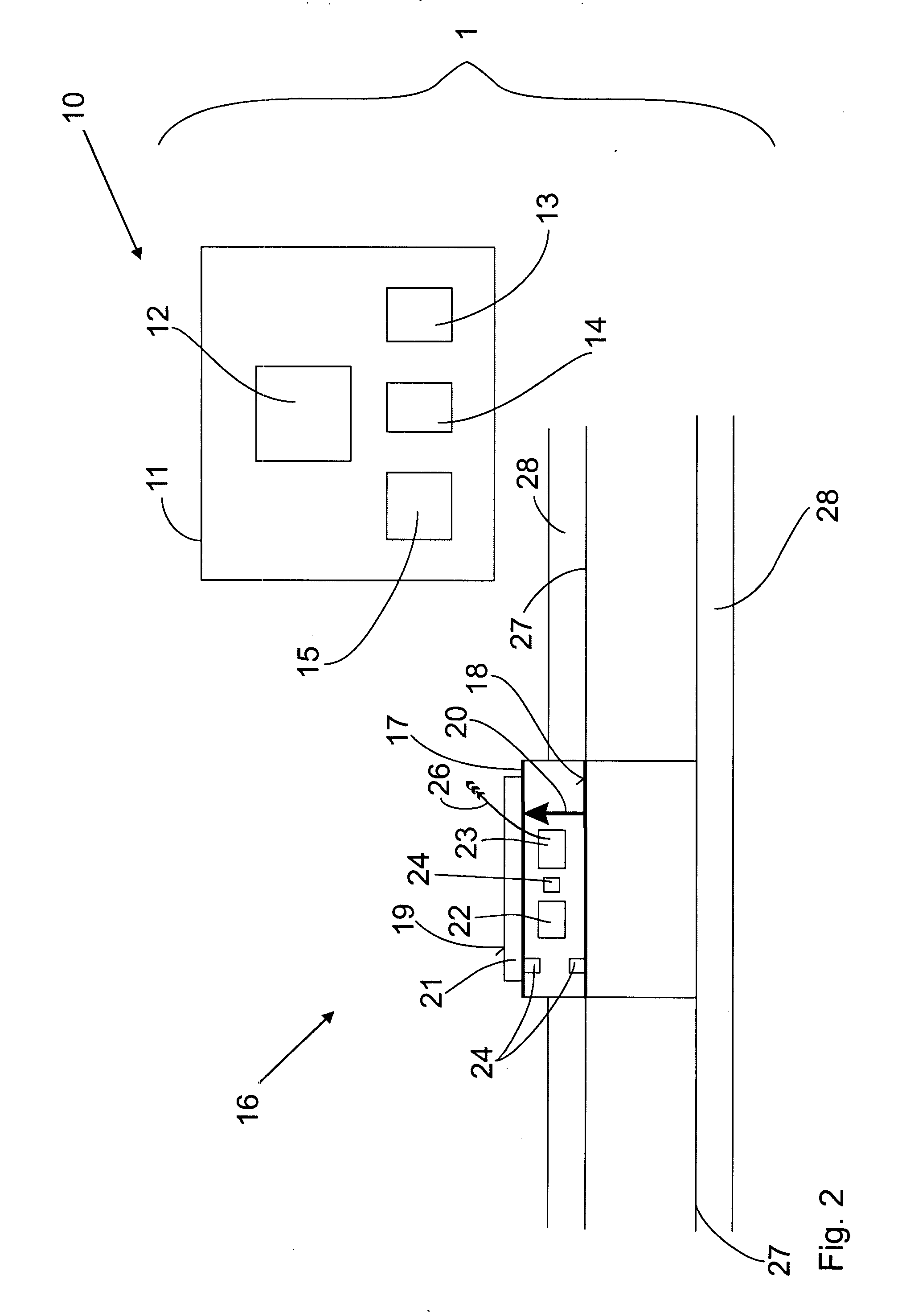
[0019]FIG. 1 shows an exemplary arrangement 1 for supplying power to a field device 10 having an enclosure 11 and a wireless communications interface 13 for data communications with a central data-processing device. A thermoelectric converter 16 is also provided in a separate enclosure 17 for supplying power to the field device 10. This thermoelectric converter converts an existing heat flow 20 between two points 18, 19 at different temperatures into electrical power and supplies this generated electrical power to the field device 10 via one or more electrical wires 25. The thermoelectric converter 16 is itself arranged by means of a holder on a pipeline 27 carrying process media, for example, with a converter side 18 oriented towards the process resting directly or indirectly on the pipeline 27 carrying process media. The temperature of the pipeline 27 is thereby to be transferred to the converter side 18 oriented towards the process. Thermal conduction materials can be provided fo...


PUM


Abstract

An arrangement is disclosed for supplying power to a field device used to monitor an industrial process in a plant, having an enclosure and a wireless communications interface for data communications with a central data-processing device, and having a thermoelectric converter, which converts an existing heat flow between two points at different temperatures into electrical power and supplies this power to the field device. The thermoelectric converter is arranged in a separate enclosure from the field device, and transfers the electrical power to the field device by means of electrical wires or wireless transmission.

Description

RELATED APPLICATIONS [0001] This application claims priority under 35 U.S.C. §119 to German Application 10 2006 014 444.9 filed in Germany on Mar. 29, 2006, the entire contents of which are hereby incorporated by reference in their entireties. TECHNICAL FIELD [0002] An arrangement for supplying power to a field device as disclosed relates to a thermoelectric converter and a field device. BACKGROUND INFORMATION [0003] Field devices that are equipped with a wireless communications interface, for instance a GPRS or Bluetooth interface or another energy-saving interface such as ZigBee, are known from the prior art for use in process plants. In addition to a sensor / actuator unit, which includes the actual measurement or actuation module, a control, data-acquisition and processing module and also the wireless communications interface, these field devices also comprise inside an enclosure a power generation and supply unit for the wireless supply of power to the field device. A version of ...

Claims


Application Information

Patent Timeline
Patent Type & Authority Applications(United States)
IPC IPC(8): H01L35/30
CPCH02J17/00H01L35/30H02J50/10H02J50/40H10N10/13
Inventor PIASECKI, WOJCIECHHUBER, ROBERTFLORKOWSKI, MAREK
Owner ABB (SCHWEIZ) AG
Why Eureka
Try Eureka