Combined power pack unit

Inactive Publication Date: 2009-12-03
MARADYNE CORP
View PDF36 Cites 20 Cited by
  • Summary
  • Abstract
  • Description
  • Claims
  • Application Information

AI Technical Summary

Benefits of technology

[0007]In accordance with a further aspect of the present disclosure, there is provided a hydraulic drive system for powering a hydraulic actuator. More particularly, in accordance with this aspect of the disclosure, the drive system comprises a first hydraulic pump driven by a first motor and a second hydraulic pump driven by a second motor. Also provided is an actuator assembly.

Problems solved by technology

In some spaced-limited applications, such as in vehicles

Method used


Image

  • Combined power pack unit
  • Combined power pack unit
  • Combined power pack unit

Examples


Embodiment Construction

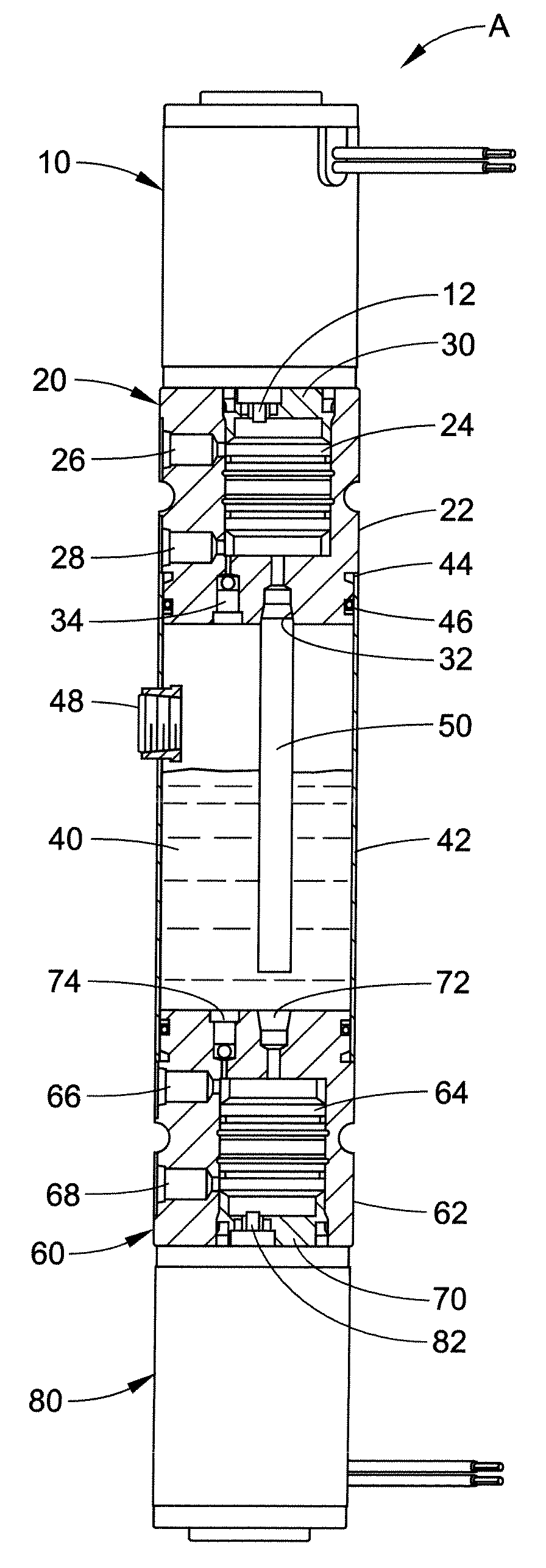
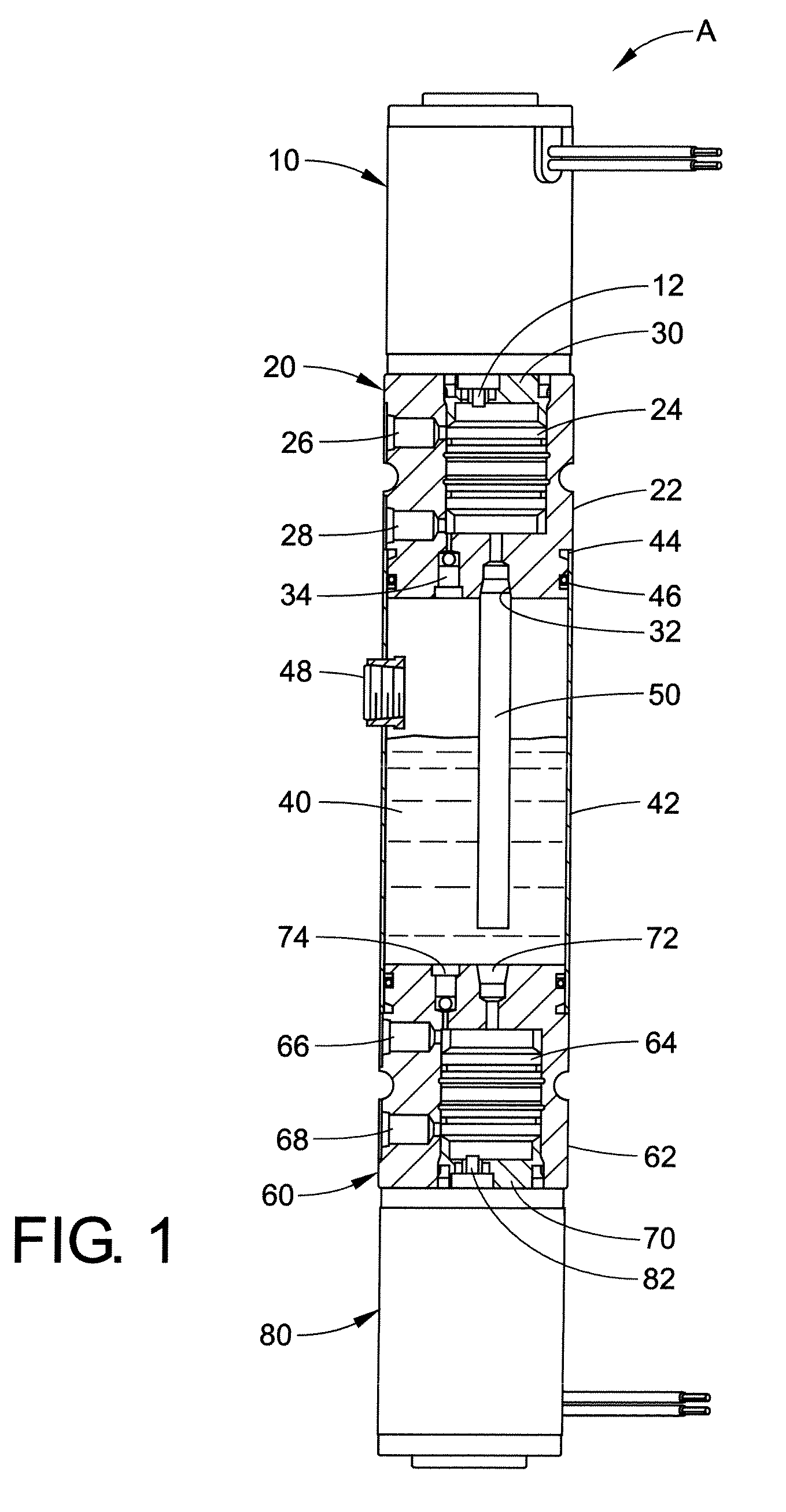
[0021]Referring now to the drawings, wherein the showings are for purposes of illustrating the several embodiments of the present disclosure only and not for purposes of limiting same, FIG. 1 shows a first embodiment of a power pack unit A. In this embodiment, there is provided a first electric motor 10. Communicating therewith is a drive shaft 12 of a first or upper pump assembly 20. If so desired, the first pump may be a hydraulic pump. The first pump assembly comprises a pump enclosure 22 which includes an internal cavity and a pump cartridge 24 disposed therein. The pump cartridge can be, for example, a compact, bi-directional pump capable of pressurizing hydraulic fluid in two opposite directions by rotation of the pump in two opposite directions. One embodiment of such a pump is illustrated in U.S. Pat. No. 6,979,185 dated Dec. 27, 2005. The disclosure of this patent is incorporated hereinto by reference in its entirety. Disclosed therein is a compact bi-rotational gear pump f...


PUM


Abstract

A power pack unit includes a first hydraulic pump including a first pump enclosure accommodating a first pump cartridge. A second hydraulic pump includes a second pump enclosure accommodating a second pump cartridge. A hydraulic fluid reservoir is positioned between the first and second hydraulic pumps. A first end of the reservoir is secured to the first pump enclosure and a second end of the reservoir is secured to the second pump enclosure. The first and second hydraulic pumps and the reservoir can extend along a common axis. First and second motors can be connected to the first and second pumps. The entire structure can extend along a common axis.

Description

BACKGROUND[0001]The present disclosure relates to hydraulic power units. Such power units generally employ an electric motor driving a hydraulic pump.[0002]Hydraulic power units are employed in a wide variety of applications. Such units provide pressurized flow to hydraulic motors, cylinders and other hydraulic components. Hydraulic power units differ from pumps because a hydraulic power unit contains a fluid reservoir, an electric motor, as well as a hydraulic pump stage driven by the electric motor. They may also include coolers to keep the hydraulic fluid at a safe working temperature. Performance specifications, physical characteristics and features are all important parameters to consider when evaluating hydraulic power units.[0003]It is common to provide an electric motor in one housing and a hydraulic pump in another housing, with the two housings being positioned in line so that the motor and pump each have their own sets of bearings and shafts that are usually engaged throu...

Claims


Application Information

Patent Timeline
IPC IPC(8): F04B49/00F16D31/02
CPCF04B23/026F04B23/06F15B15/18F15B2211/7741F15B2211/20576F15B2211/27F15B2211/20561Y10T137/86059Y10T137/86131Y10T137/86163
Inventor MOLDOVAN, IONELLSWORTH, PAUL
Owner MARADYNE CORP
Why Eureka
Try Eureka