Elastic Deformable Cushion

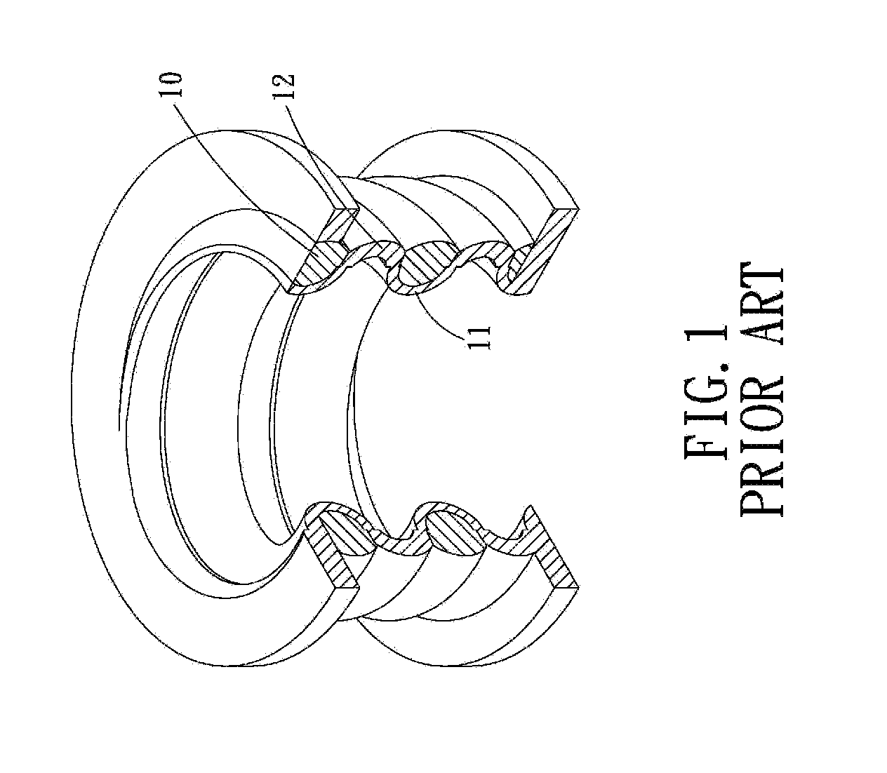
a cushion and elastic technology, applied in the field of elastic deformation cushion, can solve the problems of limited application high production cost of spiral shock absorption structure, and still the production cost of conventional elastic cushion, so as to improve the buffering effect and improve the compressive rigidity

Inactive Publication Date: 2009-12-03
YANG TENG JEN
View PDF3 Cites 9 Cited by
  • Summary
  • Abstract
  • Description
  • Claims
  • Application Information

AI Technical Summary

Benefits of technology

[0009]The primary object of the present invention is to provide an elastic deformable cushion, an elastoplastic rib of which is provided at the bearing surface with a curved portion so as to improve the compressive rigidity. On the vertical bearing surface of the elastoplastic rib piece is provided with multi layers of arc-curved portion for improving the buffering effect.
[0010]The secondary object of the present invention is to provide an elastic deformable cushion, wherein an elastoplastic curved piece made of elastoplastic material, at least two grooves are formed in an outer surface of the elastoplastic curved piece, and the at least two grooves in the outer surface of the elastoplastic curved piece are separated from and not in communication with one another. In an inner surface of the elastoplastic curved piece is formed a groove opening in an opposite direction to and located between the at least two grooves in the outer surface of the elastoplastic curved piece. The elastoplastic ribs are formed in the at least two grooves in the outer surface of the elastic curved piece. In this case, the elastic deformable cushion in accordance with the present invention can be easily produced, and the resultant production cost will be reduced.

Problems solved by technology

However, this conventional elastic cushion still has some disadvantages as follows:
First, the elastoplastic spiral member 10 and the elastoplastic spiral strip 11 must be combined together and produced in a helical manner, however, the production cost of such spiral shock-absorbing structure is pretty high.
Second, the shape of the elastoplastic spiral member 10 and the elastoplastic spiral strip 11 has been confined to the helical cylinder, thereby, the applicability of the conventional elastic cushion is limited.

Method used


Image

  • Elastic Deformable Cushion
  • Elastic Deformable Cushion
  • Elastic Deformable Cushion

Examples


Embodiment Construction

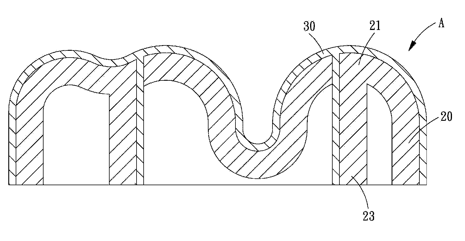
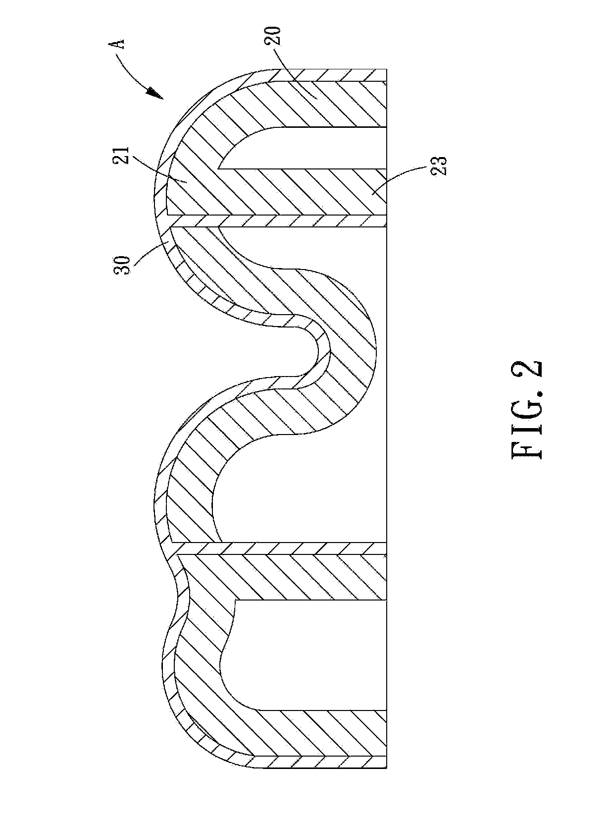
[0028]Referring to FIGS. 2-4, an elastic deformable cushion A is shown and generally including a plurality of elastoplastic ribs 20 and an elastoplastic curved piece 30, both of which are to be disposed on a bearing surface of a shock-absorb object (such as: sole and the buffering equipment). The elastic deformable cushion is made by plastic ejection molding (or reimplantation), therefore the plastic connecting portion of the respective elastoplastic ribs 20 and that of the elastoplastic curved piece 30 are integrally and firmly connected to each other.

[0029]The elastoplastic ribs 20 are separated from one another by a buffering distance 22 and are stacked one on top of another (not in a helical manner).

[0030]The elastoplastic curved piece 30 is a thin piece made of hard elastoplastic material. At least two grooves 34 are formed in an outer surface of the elastoplastic curved piece 30, and the at least two grooves 34 in the outer surface of the elastoplastic curved piece 30 are sepa...


PUM


Abstract

An elastic deformable cushion comprises: an elastoplastic curved piece made of elastoplastic material, and at least two elastoplastic ribs. At least two grooves are formed in an outer surface of the elastoplastic curved piece, and the grooves are separated from and not in communication with and one another. In an inner surface of the elastoplastic curved piece is formed a groove opening in an opposite direction to and located between the at least two grooves in the outer surface of the elastoplastic curved piece. The at least two elastoplastic ribs are formed in the at least two grooves in the outer surface of the elastoplastic curved piece, the elastoplastic ribs are integral with the elastoplastic curved piece, and each of the two elastoplastic ribs have a curved portion.

Description

[0001]This application is a continuation of part of U.S. patent application Ser. No. 11 / 389,755, which claims the benefit of the earlier filing date of Mar. 27, 2006. Claim 1 of this application is revised from the previous claim 1 of the U.S. patent application Ser. No. 11 / 389,755, claims 2-5 of this application correspond to the previous claims 2-5 of the U.S. patent application Ser. No. 11 / 389,755.BACKGROUND OF THE INVENTION[0002]1. Field of the Invention[0003]The present invention relates to an elastic deformable cushion, and more particularly to an elastic deformable cushion that is integrally formed by soft elastoplastic rib and hard elastoplastic rib piece, through this structure, the damper performance and elastic recovery function of the elastic deformable cushion is improved.[0004]2. Description of the Prior Arts[0005]Shock-absorbing structure is widely used, such as on the machine, the shoes and the article for daily use. U.S. Pat. No. 6,749,187 discloses a conventional s...

Claims


Application Information

Patent Timeline
Patent Type & Authority Applications(United States)
IPC IPC(8): B32B3/30B32B3/00
CPCA43B1/0018A43B13/181Y10T428/24479F16F3/093Y10T428/2457F16F1/3713
Inventor YANG, TENG-JEN
Owner YANG TENG JEN
Why Eureka
Try Eureka