

Assembled battery formed by stacking a plurality of flat cells
a technology of flat cells and assembled batteries, applied in the field of assembled batteries, can solve the problems of shortening the battery life, easy transmission of vibrations and impacts, and insufficient heat releas
- Summary
- Abstract
- Description
- Claims
- Application Information
AI Technical Summary
Benefits of technology
Problems solved by technology
Method used
Image

Examples
example 1
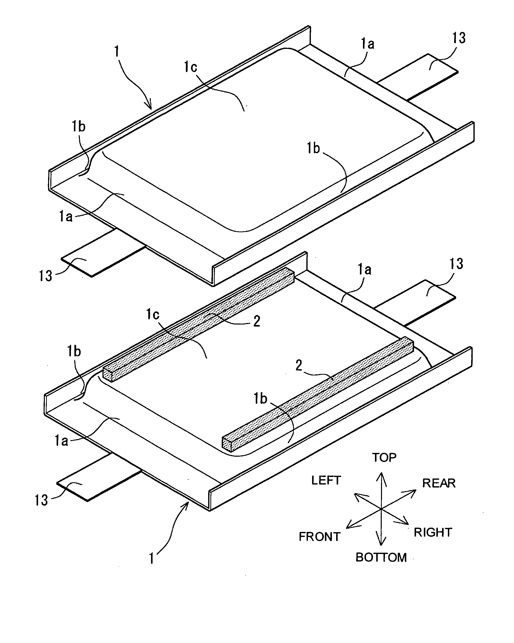
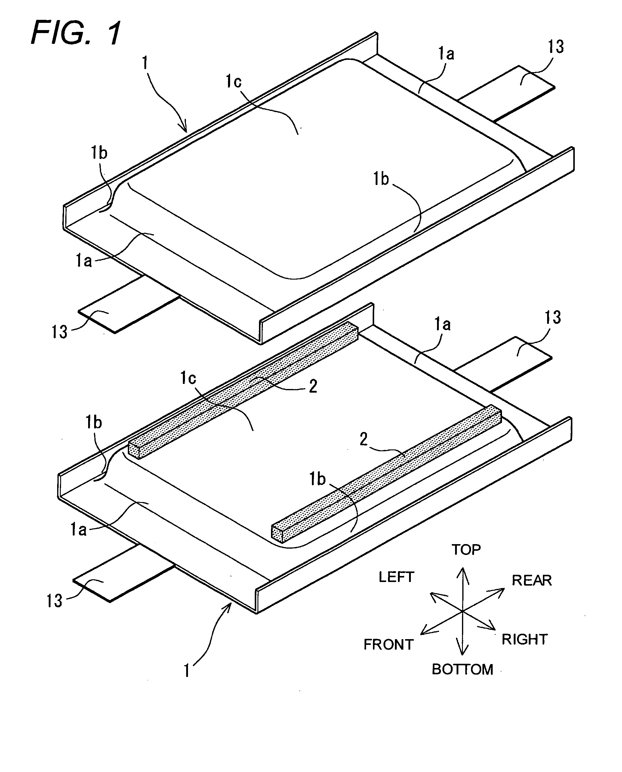
[0078]As shown in FIG. 1 and FIG. 2, Example 1 shows the case that rod-form spacers 2 are disposed between opposed flat faces 1c of vertically stacked neighboring nonaqueous electrolyte secondary cells 1 (Example of the second invention). These spacers 2 were in a square rod form with almost same length as the distance of the flat faces 1c of the nonaqueous electrolyte secondary cells 1 in the front and rear direction and arranged in the right and left end parts of the opposed flat faces 1c while the longitudinal directions were in the front and rear directions. The respective spacers 2 may be composed of hard resin-molded products; however, they are preferably composed of elastic bodies of a rubber, or the like. Further, the respective spacers 2 are preferable to be stuck to the flat faces 1c by using a both-sided adhesive tape or an adhesive so as not to be displaced easily.
[0079]In the nonaqueous electrolyte secondary cells 1 shown in Example 1, the right and left side end parts ...
example 2
[0085]As shown in FIG. 4 and FIG. 5, Example 2 shows the case that frame-form spacers 4 are disposed between opposed side end parts 1b of vertically stacked neighboring nonaqueous electrolyte secondary cells 1 (Example of the third invention). These frame-form spacers 4 were used each in the right side end parts 1b and in the left side end parts 1b. These respective spacers 4 are frame bodies of resin thin sheets made by resin molding and each composed of an upper support part 4a and a lower support part 4b. The upper support part 4a is a part formed by curving a resin thin sheet in the recessed state so as to support one side end part 1b facing downward and the end parts 1a in its front and rear side of the upward neighboring nonaqueous electrolyte secondary cells 1. The lower support part 4b is a part formed by curving a resin thin sheet in the recessed state so as to support one side end part 1b facing upward and the end parts 1a in its front and rear side of the downward neighbo...
example 3
[0089]As shown in FIG. 6 and FIG. 7, Example 3 shows the case that spacers 5 are disposed all between opposed flat faces 1c and between opposed side end parts 1b (in both right and left sides) of vertically stacked neighboring nonaqueous electrolyte secondary cells 1 (Example of the fourth invention according to the present invention). These spacers 5 were plate form produced by resin molding and have each cell support parts 5a in both right and left end parts. The cell support parts 5a were parts of both end parts of each spacer 5 projected in the up and down direction.
[0090]The cell support parts 5a were formed while being curved in a recessed state to support the side end parts 1b of the vertically opposed nonaqueous electrolyte secondary cells 1. Further, triangular triangle holes 5b penetrating the cell support parts 5a in the front and rear direction are formed. In addition, although the right and left side end parts 1b were not folded in the nonaqueous electrolyte secondary c...
PUM
 Abstract
Description
Claims
Application Information