Hydraulic Auto-Tensioner

a technology of hydraulic auto-tensioner and hydraulic pressure, which is applied in the direction of belt/chain/gearing, mechanical equipment, belts, etc., can solve the problems of certain amount of foaming, and achieve the effect of preventing the occurrence of deterioration of the auto-tensioner function

Inactive Publication Date: 2009-12-03
OTICS CORP +1
View PDF13 Cites 5 Cited by
  • Summary
  • Abstract
  • Description
  • Claims
  • Application Information

AI Technical Summary

Benefits of technology

[0012]According to the hydraulic auto-tensioner of the present invention, the mingling of air with oil can be reduced, thereby preventing de

Problems solved by technology

Note, however, that a certain a

Method used


Image

  • Hydraulic Auto-Tensioner
  • Hydraulic Auto-Tensioner
  • Hydraulic Auto-Tensioner

Examples


examples

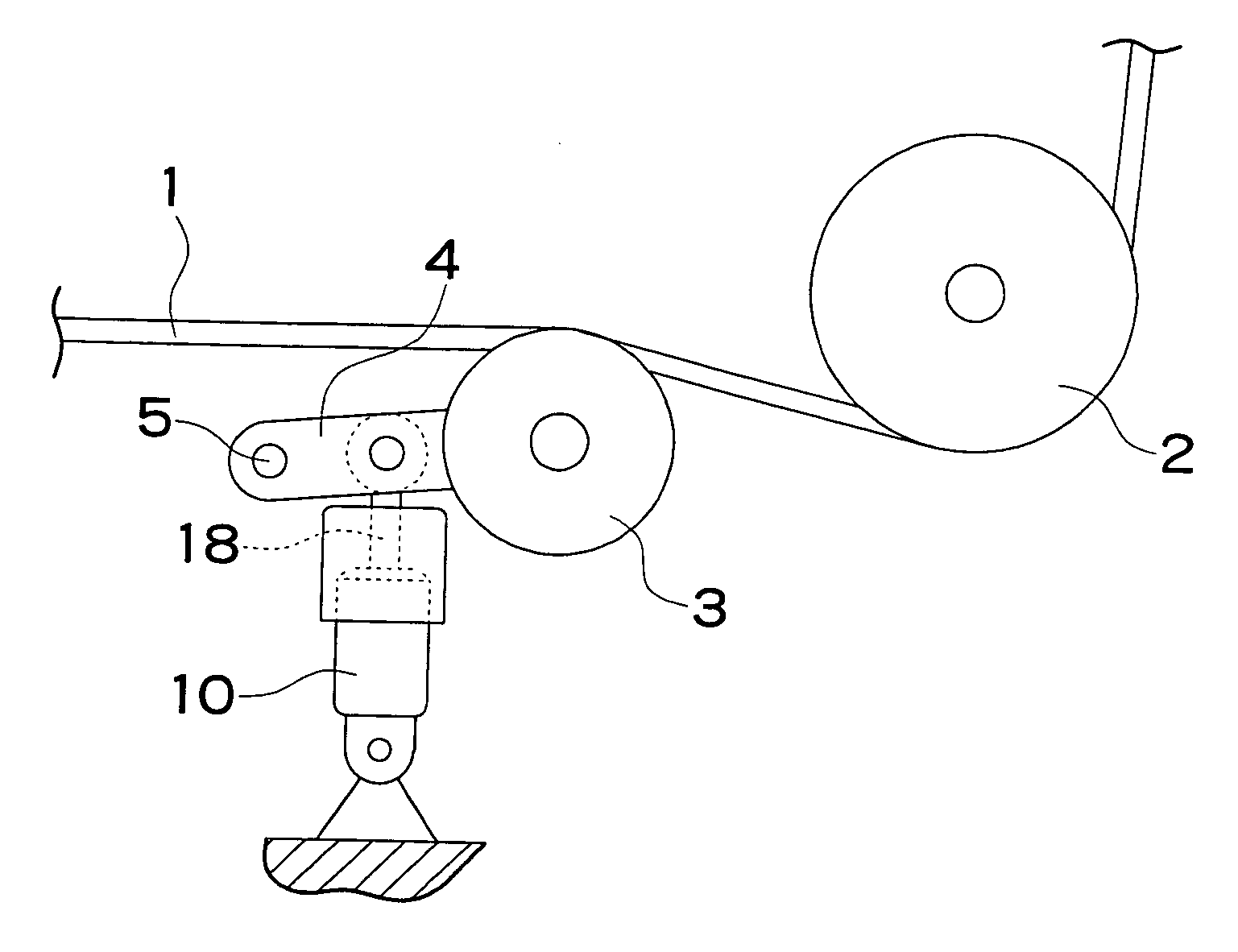
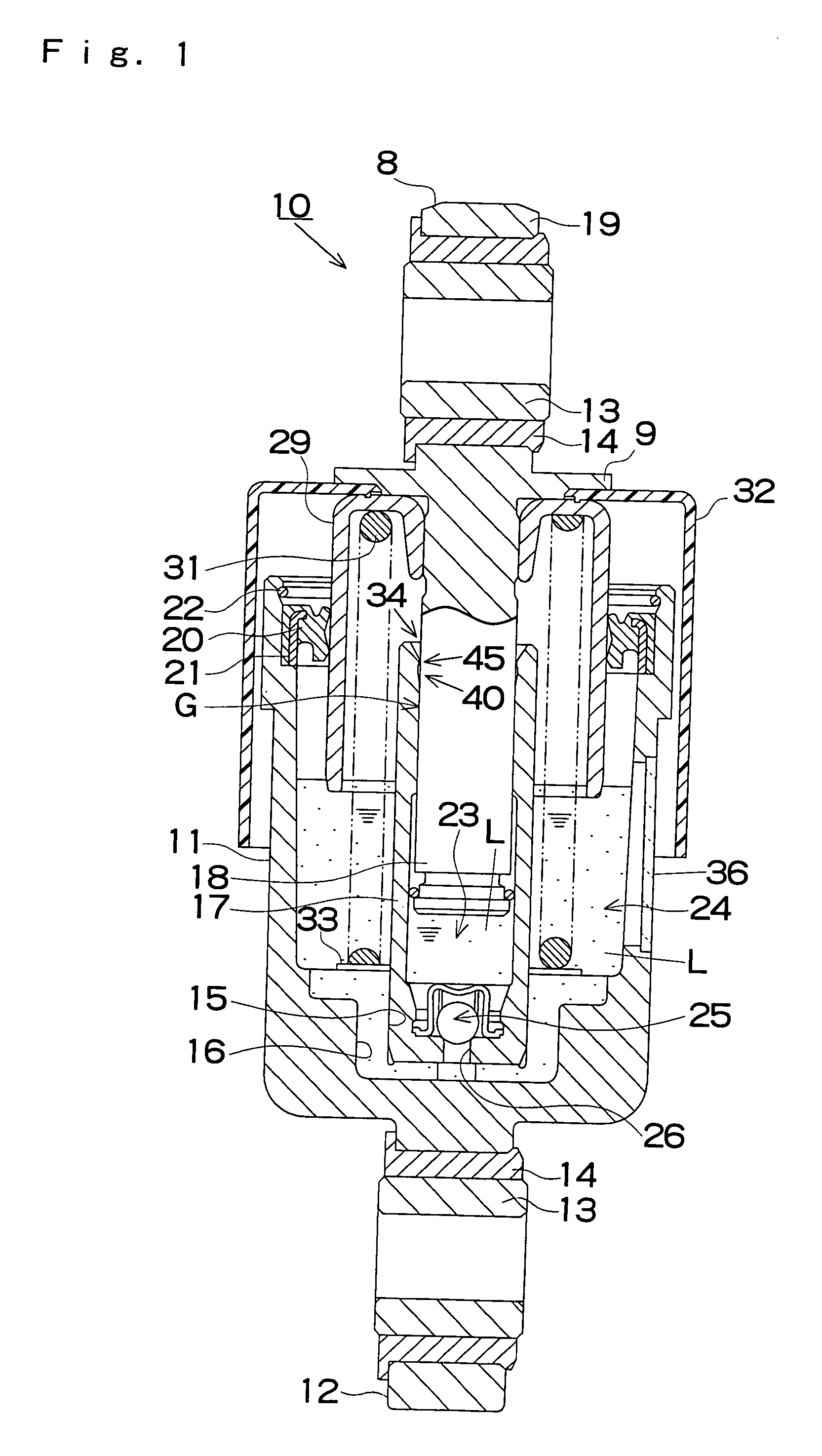
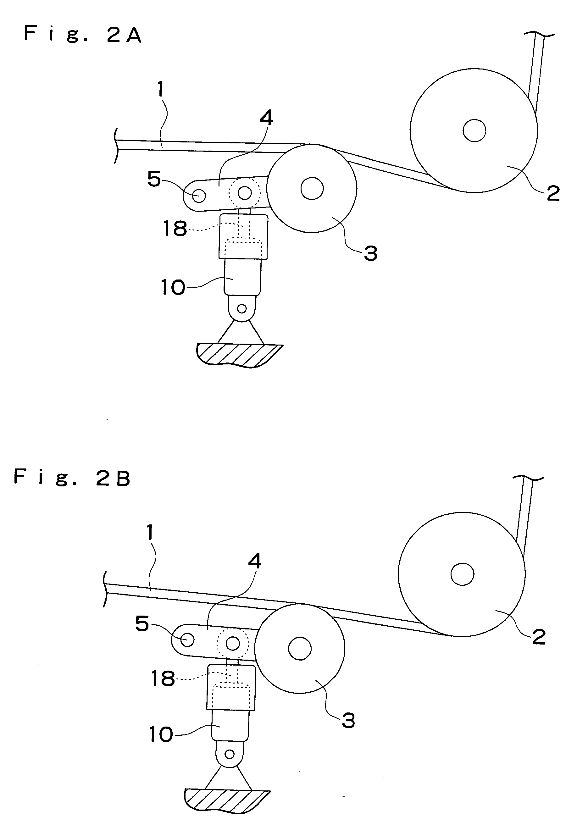
[0023]A specific embodiment of the hydraulic auto-tensioner according to the present invention will be described below with reference to FIGS. 1 to 3. A hydraulic auto-tensioner 10 according to this embodiment has a casing 11 in the shape of a closed-end tube, and a ring-shaped collar 13 is provided on an attachment portion 12 formed integrally with a lower surface of the casing 11 so as to be capable of rotating via a dry bearing 14. An insertion receiving portion 15 having a reduced diameter is provided on an inner peripheral lower portion of the casing 11, and an oil groove 16 is formed in a recessed manner in an inner peripheral surface of the insertion receiving portion 15 and an inner bottom surface of the casing 11.

[0024]A closed-end cylinder 17 having a slightly smaller outer diameter than the inner diameter of the casing 11 is inserted into the casing 11, and a lower end portion thereof is forcibly inserted into and fixed to the insertion receiving portion 15. A rod-shaped ...


PUM


Abstract

A hydraulic auto-tensioner includes a high-pressure oil chamber and a low-pressure oil chamber, and oil (L) in the high-pressure oil chamber passes through a clearance (G) between a cylinder (17) and a piston portion (18) of a plunger and leaks into the low-pressure oil chamber from an end of the clearance (G) near an end surface of the cylinder (17). A recessed groove (40) is provided in an inner peripheral surface of the cylinder (17) by a conical surface (41) having a groove angle of 5 to 15 degrees from the end of the clearance (G), a throttle portion (45) projecting onto the piston portion (18) side is provided further toward the end surface side of the cylinder than the groove (40) in the inner peripheral surface of the cylinder (17), and a throttle gap (A) larger than the clearance (G) is formed between the throttle portion (45) and the piston portion (18).

Description

TECHNICAL FIELD[0001]The present invention relates to a hydraulic auto-tensioner for automatically applying appropriate tension to a transmission member such as a belt or chain.BACKGROUND ART[0002]As shown in FIG. 8, in many hydraulic auto-tensioners 100, a low-pressure oil chamber 106 is formed between a casing 101 and a cylinder 102 provided on the inside thereof, a high-pressure oil chamber 105 pressed by a plunger 103 is formed in the interior of the cylinder 102, and by biasing a return spring 104 in a direction for causing the plunger 103 to retreat, oil L flows in a single direction from the low-pressure oil chamber 106 to the high-pressure oil chamber 105 via a check valve 107. Meanwhile, during an overload, when the plunger 103 advances deeply into the cylinder 102, the oil L in the high-pressure oil chamber 105 leaks into the low-pressure oil chamber 106 through a clearance G between the cylinder 102 and a piston portion 111 of the plunger 103 from an end of the clearance ...

Claims


Application Information

Patent Timeline
IPC IPC(8): F16H7/12F16H7/08F16H7/22
CPCF16H7/1236F16H2007/0859F16H2007/0806
Inventor KAWAHARA, KAZUNORIUCHIDA, YASUYUKIKATO, YUJIOTA, TAKAYOSHIKAWARA, HIROYUKI
Owner OTICS CORP
Why Eureka
Try Eureka