Paper Scoring System

a scoring system and paper technology, applied in the field of rotary systems and equipment, can solve the problems of limited flexibility of the approach, and large diameter of the o-ring

Inactive Publication Date: 2009-12-03
TECH NI FOLD LTD
View PDF29 Cites 6 Cited by
  • Summary
  • Abstract
  • Description
  • Claims
  • Application Information

AI Technical Summary

Benefits of technology

[0014]An advantage of forming the resilient annular scoring tool with a base in addition to the scoring feature, arises from the fact that the base is not constrained by the functional requirements of the scoring feature. Scoring features of different sizes and shapes can be used in conjunction with bases of the same size and shape, to be accommodated by the same groove in the rigid roller. Secondly, the base can have a much larger width (axial direction) than the scoring feature or blade, to impart increased strength and structural stability to the scoring tool. For example, a base supporting a 0.025 inch (width) scoring blade can have a width of 0.125 inches. The much larger scoring tool can be elastically elongated (stretched) with minimal concern that the elongation will exceed elastic limits of the polymeric materials typically involved. The larger surface area of the base is contiguous with a much larger surface area of the roller, in particular the groove, which provides a more secure and stable mounting of the scoring tool.
[0015]Another aspect of the present invention is a scoring roller assembly for use in a paper processing system. The roller assembly includes a cylindrical first roller rotatable on a first axis and having a circumferential tool-retaining groove with a first width. The assembly includes a set of scoring tools comprising a first flexible scoring tool having a first annular base and a first annular scoring feature narrower than the first annular base and projecting radially outward from the first annular base, and a second flexible scoring tool having a second annular base and a second annular scoring feature narrower than the second annular base and projecting radially outward from the second annular base. Each of the first and second annular bases is adapted for a nesting engagement within the tool-receiving groove to removably secure the associated scoring tool for rotation with the roller. The first and second scoring features have respective and different first and second radial-axial profiles.

Problems solved by technology

While suitable for particular applications, this approach has limited flexibility.
Other disadvantages arise from the nature of the O-rings, which when suitable for scoring have extremely small diameters, e.g. in the range of 0.025 to 0.035 inches (0.63-0.88 mm).
This renders the O-rings subject to excessive force concentrations that can lead to tearing, cracking or other damage when the rings are stretched to install them onto a male roller.
Also, since the tensile force necessary to positively secure the O-rings on the roller is large in comparison to the O-ring cross-sectional area, the ring is susceptible to cold flow and relaxation of the tension, which over time diminish the tension and provide a less secure mounting of the ring.

Method used


Image

  • Paper Scoring System
  • Paper Scoring System
  • Paper Scoring System

Examples


Embodiment Construction

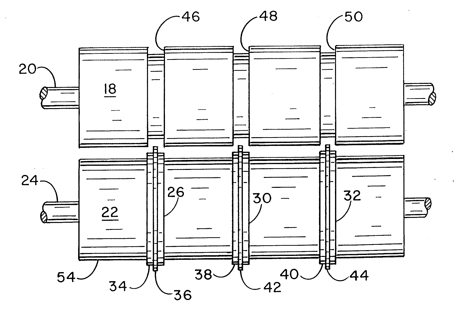
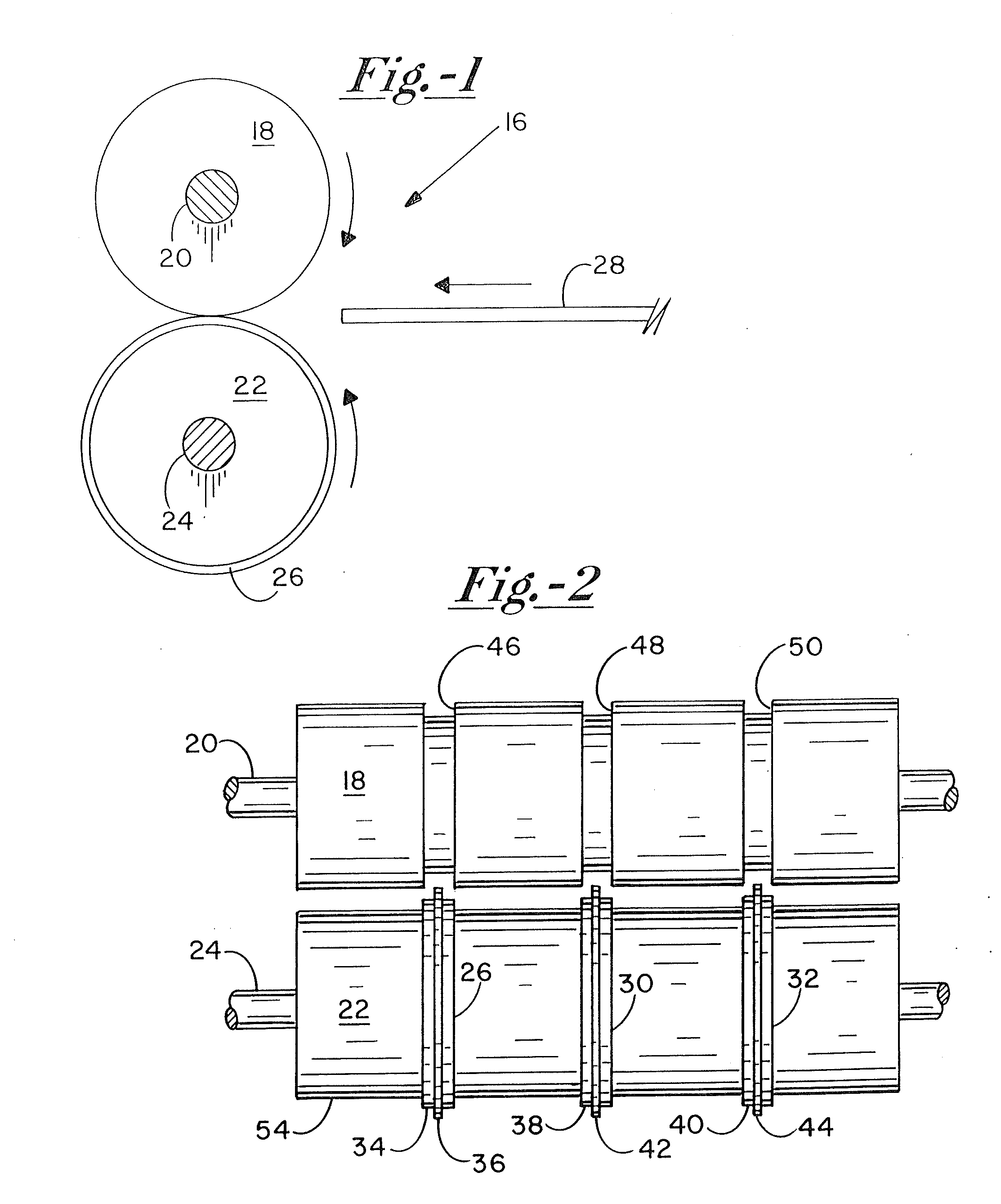
[0029]Turning now to the drawings, where shown in FIG. 1 a system 16 for processing paper and cardboard stock, more particularly a scoring or creasing stage of the system. System 16 includes a female roller 18 mounted on a shaft 20 for rotation with the shaft about a female shaft axis that would appear as a point if represented in FIG. 1. A male roller 22 is mounted on a shaft 24 for rotation therewith about a male shaft axis parallel to the female shaft axis. The male roller supports an annular, resilient scoring tool or scoring ring 26, integrally so that scoring tool 26 rotates with the male roller.

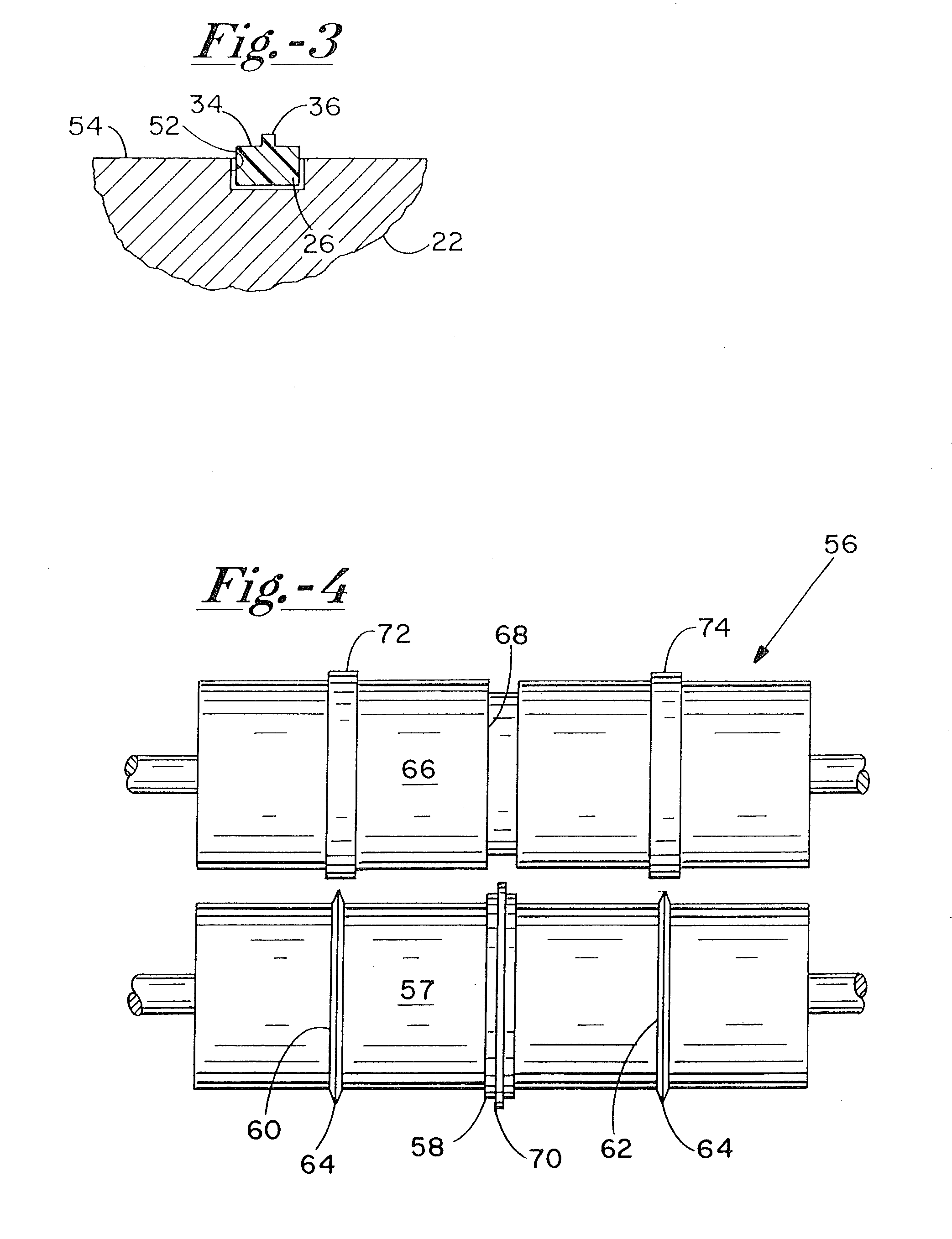
[0030]Paper stock 28, which can take the form of a continuous web or separate sheets, is fed toward the interface of rollers 18 and 22. The rollers are counter-rotated, i.e. in opposite direction as indicated by the arrows, to move the paper stock leftward as viewed in the Figure. Scoring tool 26, in cooperation with a groove formed in female roller 18 (FIG. 2), forms a linear score or...


PUM


Abstract

A scoring system uses a grooved roller and a variety of resilient annular scoring tools. The scoring tools have scoring features or blades of different profiles, and further have annular bases uniform in width to enable their interchangeable installation into one or more tool-retaining grooves formed into the roller. The bases are much larger than the scoring features to provide increased strength and durability, along with more stable mounting of the scoring tool. In one version, a single roller assembly is formed by removably securing processing sleeves and spacing sleeves on a common support member.

Description

CROSS REFERENCE[0001]This application is a divisional of U.S. Non-Provisional patent application Ser. No. 11 / 749,420, filed on May 16, 2007 and entitled “Paper Scoring System,” the entirety of which is incorporated by reference herein.BACKGROUND OF THE INVENTION[0002]The present invention relates to rotary systems and equipment for high-speed processing of paper and card stock, and more particularly to systems and equipment designed to score (crease) and perforate such stock.[0003]For many years, rotary devices have been used to cut, score and perforate paper and card stock in recognition of the considerably higher throughput rates afforded by such devices. In essence, the stock is fed between a processing (e.g. scoring) disc or roller and a counter-directionally rotated back-up disc or roller. The arrangement is particularly well-suited to process a continuous web of paper or card stock. U.S. Pat. No. 1,091,204 (Ferres) illustrates an early approach.[0004]More recently, rigid proce...

Claims


Application Information

Patent Timeline
Patent Type & Authority Applications(United States)
IPC IPC(8): B31B1/14B31B1/36B31B50/25B31B50/36
CPCB31F1/10
Inventor SCHAACK, DENNIS R.
Owner TECH NI FOLD LTD
Why Eureka
Try Eureka